
Ac Wiring Locator Circuit
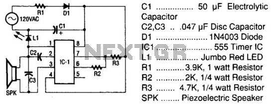
The circuit operates effectively by first converting the incoming AC voltage into a usable DC voltage through the half-wave rectification process. Diode D1 is crucial in this conversion, allowing current to flow in only one direction, thus preventing reverse current that could potentially damage other components. The current-limiting resistor R1 ensures that the diode operates within safe parameters, preventing excessive current flow that could lead to overheating or failure.
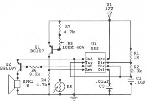
Capacitor C1 acts as a storage element, smoothing out the rectified voltage to provide a stable DC voltage to the 555 timer IC (IC1). The 555 timer is set up in astable mode, where it continuously oscillates between high and low states, generating a square wave output. The frequency of oscillation is determined by the values of resistors R2 and R3 in conjunction with capacitor C2. The specific values of these components can be adjusted to set the desired frequency of the output signal.
The output from pin 3 of the 555 timer is used to drive a piezoelectric speaker (SPK), which converts the electrical signal into sound waves, providing an audible indication of the presence of AC voltage. This feature is particularly useful in applications where visual indicators are not sufficient or practical.
In addition to the audio signal, the circuit includes an LED (L1) that serves as a visual indicator. When AC voltage is present, the LED lights up, providing a clear and immediate indication of voltage presence. This dual indication method—both auditory and visual—enhances the usability of the tester, making it effective in various applications where AC voltage detection is required.
Overall, this circuit design is compact and efficient, suitable for quick diagnostics and monitoring of AC voltage in various electronic and electrical systems. The tester consists of a rectifier circuit and a multivibrator circuit. The ac voltage is half-wave rectified by diode D1 and stored in capacitor CI. Resistor Rl is used to limit the current through D1 to a safe value. The voltage stored across CI supplies ICi operating power. The IC, the versatile 555 timer, is configured to operate as a multivibration whose operating frequency is determined by C2, R2, and R3. The output of ICI, on pin 3, is coupled to a piezoelectric speaker (SPK), which gives an indication of the presence of ac.
An LED (LI) also lights when ac is present. 🔗 External reference
Related Circuits
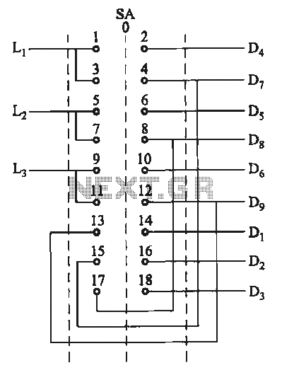
The motor switch control circuit depicted in the figure provides two speed settings for counter-steering, allowing for operation at two speeds in opposite directions. The motor switch control circuit is designed to facilitate the operation of a motor at two...
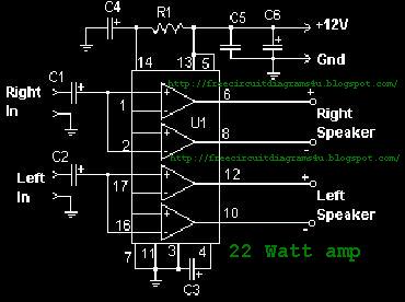
The function of the sound level display circuit is to enhance the appearance of an amplifier circuit or a radio player. It provides an impressive visual representation of audio levels. The sound level display circuit serves as a visual indicator...
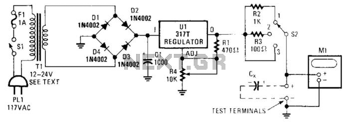
Sometimes electrolytic capacitors that are stored for a period may exhibit high leakage currents. Before utilizing these capacitors, it may be necessary to reform them. This power supply can be employed for the reforming process. Adjust resistor R4 according...
The following circuit illustrates a Sun Up Alarm Light Alarm Circuit Diagram. This circuit is based on the 555 Integrated Circuit (IC). Features include simplicity and cost-effectiveness. The Sun Up Alarm Light Alarm Circuit employs the 555 timer IC in...
The circuit is designed to be low cost. It uses a PIC12C508 to perform the control functions and standard 40 kHz piezo transducers. The drive to the transmitting transducer can be simply driven directly from the PIC. The 5V...
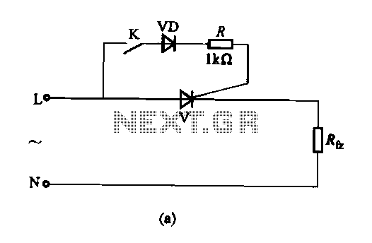
The thyristor AC switch circuit is not triggered, due to its simplicity, cost-effectiveness, and non-contact operation, making it widely utilized. The circuit is illustrated in Figure 16-43. It consists of single-phase thyristor switching circuits. Figure 16-43 (a) depicts a...
Warning: include(partials/cookie-banner.php): Failed to open stream: Permission denied in /var/www/html/nextgr/view-circuit.php on line 713
Warning: include(): Failed opening 'partials/cookie-banner.php' for inclusion (include_path='.:/usr/share/php') in /var/www/html/nextgr/view-circuit.php on line 713