
Novel White LED Torch
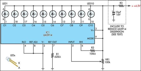
The circuit employs the LM3914 integrated circuit, which is designed for driving LED displays in a bargraph configuration. The main components include a variable resistor (VR1) that adjusts the input voltage to the LM3914, enabling control over the brightness of the connected LEDs. The operation of the circuit is straightforward: as the resistance of VR1 changes, the voltage at pin 5 of the LM3914 varies accordingly, leading to a change in the number of LEDs illuminated. This creates a visual representation of the voltage level provided by VR1.
R2 serves to ensure that the last LED (LED 10) has a defined threshold for activation, preventing it from turning on until a certain voltage level is reached. R1 is crucial for current regulation, ensuring that each LED receives a consistent 20mA of current, which is essential for maintaining uniform brightness across all LEDs while preventing damage due to overcurrent.
In terms of power management, the circuit's design allows for a low quiescent current when all LEDs are off, making it efficient for portable applications. The recommendation to include resistor R3 becomes critical when operating at higher supply voltages, as it helps manage the thermal performance of the LM3914, ensuring it operates within safe limits. The decoupling capacitor (10 µF) is necessary to stabilize the power supply, filtering out any noise that could affect the performance of the LM3914 and the overall circuit stability.
This configuration is particularly useful for applications requiring adjustable brightness in LED lighting, such as in portable LED flashlights or indicators, where battery life and component size are critical considerations. The simplicity and efficiency of the design make it an attractive option for various electronic projects involving LED displays.Although this design is reproduced directly from the manufacturer`s datasheets, its use in this application is rather novel. Originally intended for high-visibility LED bargraph readouts, here the LM3914 is used as the basis of a 10-step variable brightness current-regulated white LED torch!
The circuit has only four components in the control and regulation circuit: R1, R2, VR1 and the LM3914. The circuit can be built directly on the pins of the LM3914 to produce a package not much bigger than the LM3914 itself. The LM3914 is set to operate in bargraph mode so that the LEDs light progressively as its input signal increases.
This signal comes from the wiper of VR1, which provides a variable voltage between 0V and the supply voltage to pin 5 of the LM3914. The internal resistor ladder network of the LM3914 has its low end (pin 4) connected to ground and the high end (pin 6) connected to the supply voltage via R2.
The purpose of R2 is to give LED 10 a clear turn-on zone. Resistor R1 (620 ©) on pin 7 of IC1 sets the current through each LED to about 20mA. As VR1 is rotated from the 0V position (all LEDs off) to the supply voltage position (all LEDs on), the LEDs will progressively light. With all LEDs off, the circuit will draw about 5mA. With all LEDs illuminated, it will draw about 205mA and dissipate 307mW with a 4. 5V supply. These are nominal figures only. Actual device dissipation will depend entirely on the input voltage and LED forward voltage. In use, we recommend that a resistor (R3) be inserted in series with the positive supply, chosen so that the LM3914`s dissipation is limited to about 500mW.
Typically, this would be needed for supply voltages of 6V and higher. The inclusion of the resistor necessitates a 10 F decoupling capacitor across the supply rails. ) 🔗 External reference
Related Circuits
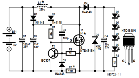
Before getting started, an acknowledgment is due. The circuit presented here employs an innovative method of controlling a flyback converter using the voltage developed across a current-sensing resistor. This approach was published by Andrew Armstrong in the July 1992...
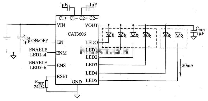
CAT3606 is a high-efficiency white LED driver. This adjustable charge pump is suitable for general-purpose, large-panel, flicker-free white LED backlighting and dual-display systems. The CAT3606 inductor boost circuit can replace conventional high-brightness backlighting requirements, thereby simplifying system design. It...
This innovative buzzer circuit incorporates a relay connected in series with a small audio transformer and a speaker. When the switch is activated, the relay is energized through the primary winding of the transformer and the closed relay contact....
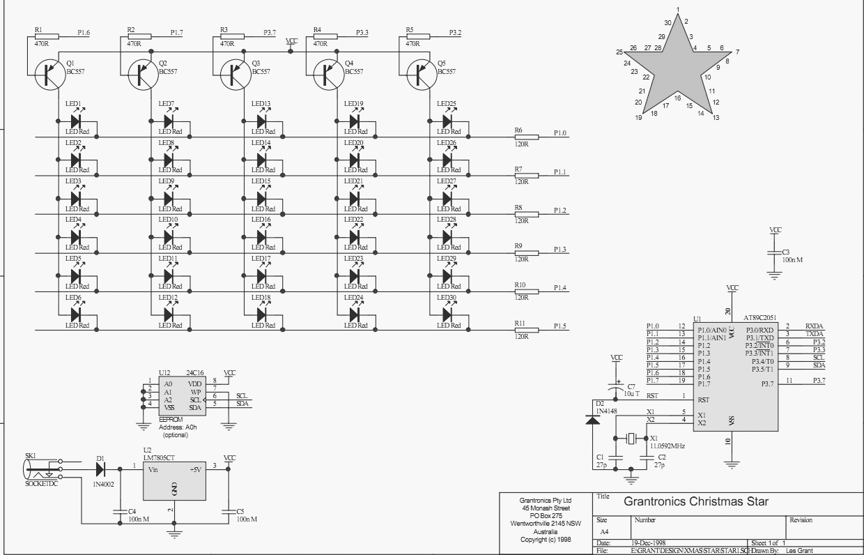
Using a PC parallel port to control external devices is a popular approach these days but I certainly couldn’t afford to tie up a PC for the few weeks leading up to Christmas just to flash a few LEDs!...

More: The input data contains a brief description with no additional context or information provided. In the realm of electronics, a circuit schematic typically serves as a visual representation of an electrical circuit. It illustrates the various components such...
The bi-directional sequencer employs a 4-bit binary up/down counter (CD4516) along with two "1 of 8 line decoders" (74HC138 or 74HCT138) to create the well-known "Night Rider" display. A Schmitt Trigger oscillator generates the clock signal for the counter,...