
Christmas Star with LEDs
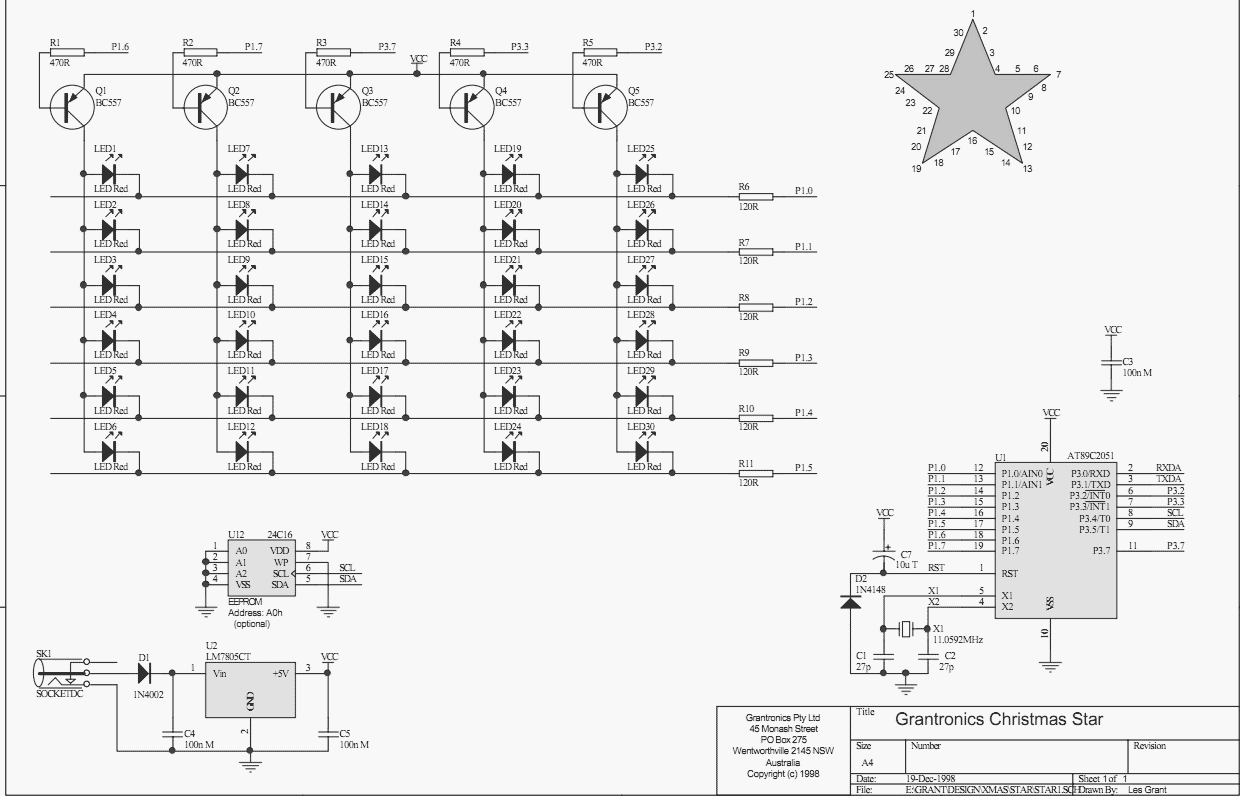
The circuit utilizes the Atmel AT89C2051 microcontroller, which serves as the primary control unit. This microcontroller is chosen for its compact size and versatile features, including 2k bytes of Flash program memory, 128 bytes of RAM, and 15 I/O lines, making it suitable for controlling the LED display effectively. The reset circuit, consisting of capacitor C7 and diode D2, ensures that the microcontroller initializes correctly upon power-up by allowing rapid discharge of C7.
An external crystal oscillator (X1) paired with capacitors C1 and C2 is employed to set the operating frequency of the microcontroller, allowing it to execute instructions at a rate of up to 24 MHz. This high frequency enables efficient processing of the multiplexing control for the LED matrix. The LEDs are arranged in an X-Y matrix configuration, allowing for the simultaneous control of multiple LEDs while minimizing the number of required I/O pins. The multiplexing technique involves illuminating each column of LEDs for a brief period (approximately 2 ms), cycling through all columns to create the appearance of a continuous display, capitalizing on the human eye's persistence of vision.
The power supply circuit is based on the widely used 7805 voltage regulator, which provides a stable 5V output to power the microcontroller and LEDs. Bypass capacitors C4 and C5 are included to filter out noise and ensure stable operation. Diode D1 offers protection against reverse polarity connections, safeguarding the circuit from potential damage. The design is capable of drawing a maximum of 150 mA when all LEDs are illuminated, with typical operation drawing significantly less current, allowing for energy-efficient performance. The regulator's thermal performance is adequate, with a manageable temperature rise, but a heatsink is recommended when operating at higher input voltages, such as 12V DC.Using a PC parallel port to control external devices is a popular approach these days but I certainly couldn’t afford to tie up a PC for the few weeks leading up to Christmas just to flash a few LEDs! Not to mention the power bill! So, why not use a small microcontroller? They are cheap and easy to use and if the design doesn’t work first time (when does it?), you simple re-program it.
Also, you can easily create something using a micro that is the equivalent of many discrete logic chips. In this case, the circuit is simple enough to lash up on VeroBoard though it is much easier to use a printed circuit board.
To do the star in discrete logic would be a nightmare! Given a few inexpensive software tools, a microcontroller such as the Atmel AT89C2051 should be just as easy to use as a handful of 4000-series CMOS chips. In my experience, the micro is usually easier! Another reason for using a micro is that micros are the future of electronics. While it is useful to know how to design with 4000-series logic, most new products require more than can be easily done in discrete logic. I believe there is actually a commercially available toaster that uses a micro! While some would say that this is an extreme example, it does indicate how far micros have entered our lives.
The Atmel AT89C2051 is a relatively recent derivative of the venerable 8051. It comes in a diminutive 20 pin skinny-DIP plastic package and contains 2k bytes of program memory, 128 bytes of RAM, 15 programmable I/O lines, on-chip oscillator, two 16 bit counter/timers, six interrupt sources and a full duplex serial port (UART). This all sounds very much like a small 8051 until we add that the program memory is re-programmable Flash with 1000 erase/write cycles, the oscillator runs to 24MHz (double that of the original 8051), the I/O pins can sink 20mA for directly driving LEDs and two I/O pins are connected to an on-chip analogue comparator!
The Hardware The heart of the hardware is, of course, the Atmel ‘2051 micro. To make it start thinking, we need a reset circuit consisting of C7. D2 forces C7 to discharge quickly when power is removed. To set how fast it thinks, we need an external crystal X1 and associated capacitors C1 and C2. Note that the crystal could be replaced by a 12MHz ceramic resonator. This allows the ‘2051 to execute an instruction every 1 or 2us. As you can see from the schematic, the 30 LEDs are connected in an X-Y matrix. Why 30 LEDs? Engineering is full of trade-offs or compromises. I wanted a 5 pointed star so the number had to be divisible by 5. For aesthetic reasons, we need an even number of LEDs per point. Six LEDs per point looked "about right". The next step up would have been 40 LEDs which would have required 13 I/O pins to drive them and a more complicated PCB. We can drive 30 LEDs from only 11 I/O pins using a process called multiplexing. The appropriate combination of LEDs in a column is switched on for a short time (about 2ms in this case).
This process is repeated for each column in turn taking 10ms for a full cycle. Provided the multiplexing is done quickly enough, the persistence of the human eye "fills in the gaps" and we see any combination of LEDs on without any flicker. The minimum practical multiplexing frequency is about 100Hz which is the frequency used by the star. The power supply uses the ubiquitous 7805 three terminal regulator with bypass capacitors C4 and C5. Diode D1 provides reverse polarity protection. The maximum current drawn by the star is about 150mA with all LEDs on but less than about 50mA for most patterns.
The maximum temperature rise of the 7805 when the star is run from a typical 9Vdc unregulated plug-pack is about 30 degrees which is quite acceptable. It gets warmer when run from a 12Vdc unregulated plug-pack and should be provided with a small heatsink.
🔗 External reference
Related Circuits
A PMOS FET switch regulator output is utilized in series with the regulator's load, as illustrated in the accompanying diagram. This represents a straightforward approach to circuit design. The described configuration employs a PMOS FET as a switching element in...
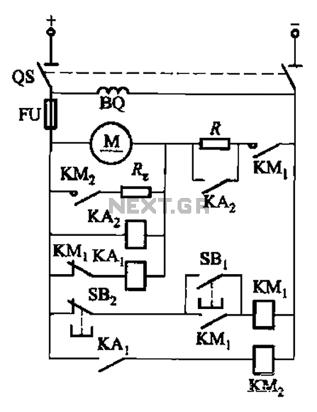
The circuit illustrated in Figure 3-196 features a starting resistance level and an undervoltage relay (KAz) that is controlled by the removal of the startup resistor. It also includes dynamic braking for shutdown purposes. The undervoltage relay (KAL) operates...
The basic circuit illuminates up to ten LEDs in sequence, synchronized with the rhythm of music or speech detected by a small microphone. The expanded version can drive up to ten strips, each containing up to five LEDs, powered...

The circuit depicted in Figure 3-41 illustrates a Y-transfer process. When contact KMi is turned off, the motor undergoes a transition in the event of a power failure. Additionally, the main contact KM3 is disconnected when KM2 is activated,...
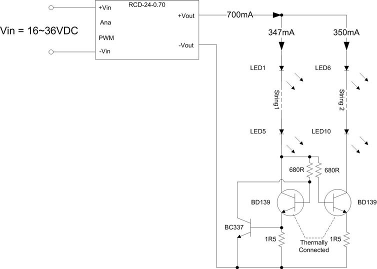
A Meanwell LED driver rated at 27V and 2300mA is available for use, intended to power two parallel strings of six LEDs each. The question arises whether to maintain the existing circuit with the same component values or to...

This simple 12-volt halogen lamp soft starter circuit extends the life of the halogen lamps by eliminating the sharp rise in the temperature of the filament. The 12-volt halogen lamp soft starter circuit is designed to mitigate the initial surge...