
led bicycle lights
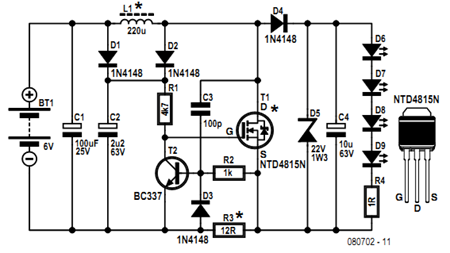
Regarding component specifications, an n-channel MOSFET with a very low RD-S(on) of 15 mΩ (at 10 V) is suggested for position T1, although a high ID rating of 35 A is not strictly necessary. While purists may prefer Schottky barrier diodes for D2 and D4, the BAT85's reverse recovery time of 4 ns is not significantly faster than that of the 1N4148, making the latter a viable option without noticeable differences in performance. A Zener diode, D5, is included as a precautionary measure against potential open circuit conditions, as the flyback converter can develop a substantial voltage when operating without a load, which could damage the MOSFET. If a higher voltage MOSFET is used, C4 may be exposed to excessive voltage if the LED connection fails. In the final prototype, D5 was a 1.3-watt, 22-volt Zener diode, but any value between 18 and 24 V is acceptable. It is important to note that with four white LEDs connected, the output voltage will be approximately 13 V.
L1 is a 9 mm diameter, 0.56 A, 220 µH inductor with low DC resistance (Farnell # 8094837); using small axial lead inductors disguised as resistors is not recommended, as even robust options may fail quickly due to shorted turns. The selection of R3 depends on the LED configuration. A typical value is 20 mA for 5 mm LEDs, with four red LEDs requiring about 12 mA, five red LEDs approximately 10 mA, and four white LEDs around 6.8 mA. Resistor R4 (1%) serves as a temporary connection for the LEDs' negative lead, allowing for voltage drop measurements to indicate the current flowing through the LEDs while adjusting R3 for the correct LED current. The efficiency of the circuit relies on the LED current, which also influences the switching frequency. At 10 mA (for four white LEDs), a switching frequency of 170 kHz was measured in the prototype, which is near the maximum tolerated by normal electrolytic capacitors. If the current is increased (for example, three white LEDs at 30 mA), the switching frequency decreases to about 130 kHz, resulting in an efficiency increase to approximately 75%. The circuit is simple enough to be constructed on stripboard, which can be configured as a single or double unit to fit available lamp housings. The double unit should comfortably fit in a 2x D cell compartment, while the single board is only slightly larger.Before getting started an acknowledgement is due, the circuit presented here uses an ingenious method of controlling a flyback converter by the voltage developed on a cur-rent sensing resistor, this was published by Andrew Armstrong in the July 1992 issue of ETI magazine. The reworked circuit is quite simple. At the instant that power is applied o nly a small current flows to charge C4 so insufficient voltage is developed on R3 to switch T2 on. Also, D1 allows C2 to charge from the 6 V battery, so R1 feeds enough voltage to switch on T1 this shunts the voltage across L1 and the current in it starts to rise. At a certain point the current which returns via R3 will develop sufficient voltage to switch on T2 which shunts the gate voltage to T1 causing it to switch off, initiating the flyback voltage from L1.
The fly-back pulse forces a current around the circuit, charging C4 and feeding the LEDs. As the return current is via the current sensing resistor R3, this keeps T2 turned on and T1 turned off, so the flyback phase is not clamped until it has given up all its energy. Capacitor C3 provides positive feedback to ensure reliable oscillation and sharpen up the switching edges.
Components D1, D2 & C2 form a bootstrap boost circuit for the MOSFET gate, although it is logic level it only guarantees the stated RD-S(on) at a Vg level of about 8 V ” by happy coincidence the combined Vf of four ultrabright red LEDs is about 8. 8 V and this is the value that the output is normally clamped to. There are some notes on the components specified. For position T1 an n-channel MOS- FET with a very low RD-S(on) of 15 m (at 10 V) Is suggested, although its high ID rating (35 A) is not strictly necessary.
Purists may wish to use Schottky barrier diodes for D2 and D4, but a quick look at the data sheet for the popular BAT85 shows that with a Trr of 4 ns it is not actually any faster than the 1N4148. It is doubtful whether the lower Vf would make any noticeable difference. Zener diode D5 has been included as a safety measure in case the output should ever find itself open circuit.
The flyback converter can develop a quite impressive voltage when run without load and would have no difficulty damaging the MOSFET. If a higher voltage MOSFET is used then C4 could easily fall prey to excessive voltage if the lead to the LED breaks.
In the final working prototype D5 was a 1. 3-watt 22-volt zener, but any value between 18 and 24 V is fine. Bear in mind that with four white LEDs on the output the voltage will be somewhere in the region of 13 V. L1 is a 9 mm diameter 0. 56 A 220 µH inductor with a low DC resistance (Farnell # 8094837); don`t even think about using those small axial lead inductors disguised as resistors even the fat ones last only a few seconds before failing with shorted turns.
On R3, this resistor is selected depending on the configuration of LEDs. A value of 20 mA is fairly typical for 5 mm LEDs, on this basis four red LEDs will need about 12 ; five red LEDs about 10, and four white LEDs about 6. 8. Resistor R4 (1 1%) is provided to use as a temporary connection for the LEDs` negative lead so the volt drop can be measured to indicate the current flowing during setting the correct LED current by adjusting R3.
The efficiency of the circuit depends on the LED current, which also determines to some extent the switching frequency. At 10 mA (4 white LEDs) 170 kHz was measured on the prototype and that`s about the maximum normal electrolytic capacitors are able to withstand.
If more current is drawn (e. g. three white LEDs at 30 mA) then the switching frequency drops to about 130 kHz and the efficiency rises to around 75%. The circuit is simple enough to construct on stripboard, which can be built as a single or double unit to suit whatever lamp housings are ready to hand.
The double unit should fit comfortably in a 2x D cell compartment and the single board is only a whisker bigger t 🔗 External reference
Related Circuits
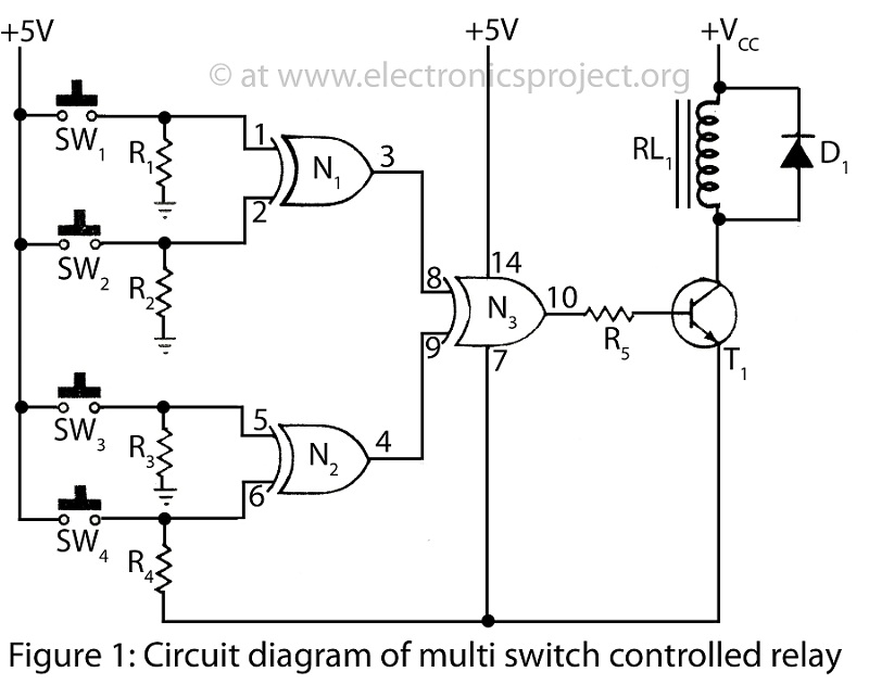
A Multi Switch Controlled Relay circuit is utilized to manage home appliances, featuring a circuit diagram that outlines the application of a multi switch-controlled relay using a single integrated circuit (IC) for various control functions. The Multi Switch Controlled Relay...

The CA3080 can be utilized as a gain-controlling device. The input signal is attenuated by resistors R1 and R2 so that a 20 mV peak-to-peak signal is applied to the input terminals. If this voltage exceeds a certain threshold,...

This is a simplified version of a white LED lamp that can be powered directly from the mains. It provides sufficient illumination for reading purposes. Capacitor Cx along... The circuit for the white LED lamp consists of several key components...
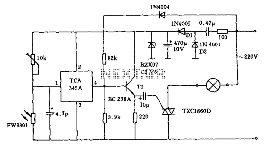
A 200W lamp switch control operates at a power supply voltage of 220V. It automatically turns the light on or off based on ambient illumination levels, specifically activating at approximately 100 lux. In low light conditions, a time-sensitive resistor...

This circuit is suitable for a small office or home environment. It can also be adapted to use a combination lock or keypad for setting and resetting. The described circuit functions as a security system tailored for small office or...
The heating element is connected in series with two back-to-back 16 amp silicon-controlled rectifiers (SCRs), which are controlled by a small pulse transformer. This pulse transformer features three identical windings: two are dedicated to providing trigger pulses to the...