
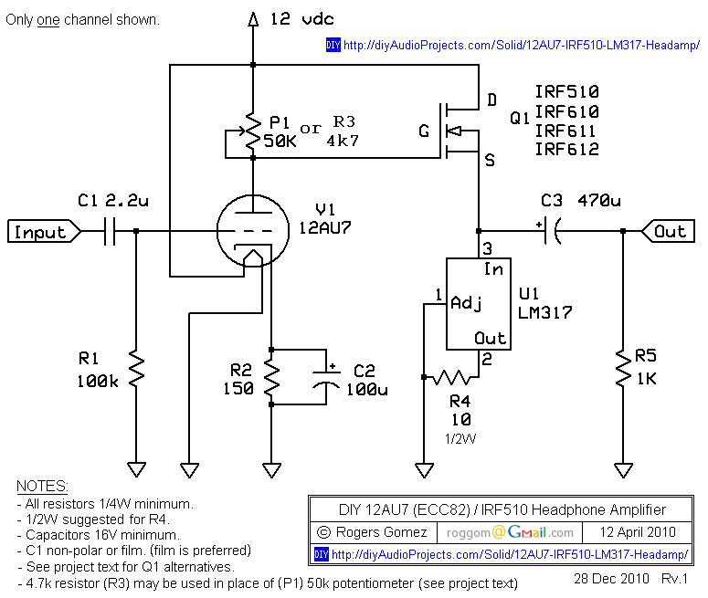
NP-100v12: DIY 12AU7 (ECC82) Tube / IRF510 MOSFET Headphone Amplifier
The NP-100v12 headphone amplifier circuit is structured to provide a user-friendly experience for builders while maintaining high audio quality. The use of the 12AU7 vacuum tube allows for a warm sound characteristic that is often sought after by audio enthusiasts. The common cathode configuration ensures that the input signal is amplified effectively, while the MOSFET source follower stage enhances current delivery, making the amplifier suitable for a wide range of headphone impedances.
In terms of construction, the circuit board layout should be designed to minimize interference and maintain signal integrity. Proper grounding techniques should be employed to reduce hum and noise, particularly in the sensitive audio path. Additionally, adequate heat dissipation measures should be considered for the MOSFET to ensure reliable performance.
The choice of power supply, whether utilizing a sealed lead-acid battery or a regulated switch-mode power supply, plays a significant role in the overall performance of the amplifier. The low ripple and noise characteristics of a battery source are particularly advantageous in headphone applications, where clarity and detail in audio reproduction are paramount.
This amplifier project not only serves as an introduction to vacuum tube technology but also provides practical experience in circuit design, component selection, and assembly techniques. As builders gain confidence and experience through this project, they may be inspired to explore more advanced audio circuits and further their understanding of electronic design principles.The NP-100v12 is a simple headphone amplifier that allows an entry level builder to experience assembling and listening to their own creation. I use the term builder as electronic experience combined with innovation which allows the creation of a device, rather than simple board stuffing.
This amplifier can take on many shapes and sizes; I especia lly like when builders reuse older devices as cases and even recycle some components from various discarded power supplies. I try to keep price at a minimum because this amplifier is very basic and allows the builder to seek out theory, and actually "listen" to their music, and grow to build more complex projects in the future.
There are plenty of wonderful websites out there that can explain tube theory, I learned from the US Navy NEETS module 6. I will not go to in depth into the theory, but will introduce you to the 12AU7 (known in Europe as ECC82).
The 12AU7 (ECC82) is a Twin Triode vacuum tube, it is very popular in the audio world because it is rather rugged and can be operated at lower voltages. You will find these tubes in vintage amplifiers and organs. They are even used in older vacuum tube volt meters and their life span can reach into decades. The 12AU7 has an amplification factor ( µ) of about 17, this is moderate as compared to its cousin the 12AX7 that comes in at 100.
For purpose of the NP-100v12 the 12AU7 tube will be used in a common cathode configuration, and the incoming signal will be amplified by approximately 10dB. The 12AU7 is usually operated at plate voltages of over 120 volts, but fortunately it can be operated at lower voltages with decent results.
As you see in the load lone graph below, we will operate in the 6 volt region. 6 volts allows enough "swing" for the signal to reach 12 volts and down to the 0 volt line. Since this amplifier is single-ended we will not be applying an external negative voltage, but due to grid leak bias the voltage does sit above common. The tube has 9 pins and follows the EIA 9A pin out configuration. Remember that pin out diagrams are always read from the bottom of the tube, this little detail may save you much rework in the future.
The great thing about this tube - it is basically two tubes in one. The other plus is that the heaters (filaments) can be powered by 6. 3 or 12. 6 volts AC or DC. In lower voltage amps, using DC for the heaters is preferred to reduce hum. For the NP-100v12 we will be using a 12 volt sealed lead acid (SLA) battery as the power supply (hence v12). The two filaments are pinned 4 to 9 and 9 to 5, with pin 9 as a center tap. One can apply 12. 6 volts across pins 4 and 5, or 6. 3 volts to pins 4 and 5 with pin 9 used for common (negative), or 6. 3 volts can be applied to pin 9 with pins 4 and 5 used as common. The power supply is rather simple and straightforward, a 12v SLA battery. The battery is rated at 1. 3 ampere-hour (Ah) and the total amplifier draw is about 400 mA, so we can expect some hours of playback between charges.
A battery is the perfect source for voltage as there is no ripple or noise that will be injected into the signal, this is very important with headphone applications. An alternate is a regulated switch mode power supply. I use a Cannon K30120 13v 1. 8A portable printer power supply. The voltage is kept constant, great filtering, and most of all there is a built in over current protect.
These power supplies can easily be found in thrift stores, the cost is miniscule to building a similar supply. It is important that the power supply be regulated to keep the unwanted noise levels low. The circuit consists of two stages: 1. a common cathode tube volt amp stage (gain), 2. a MOSFET source follower for current gain (with a LM317 voltage regulator IC configured as a constant current source ).
Since most headphones are less than 50 ohms a little current is necessary to run them efficiently. A Bipolar Junction Transistor (BJT) 🔗 External reference
Related Circuits
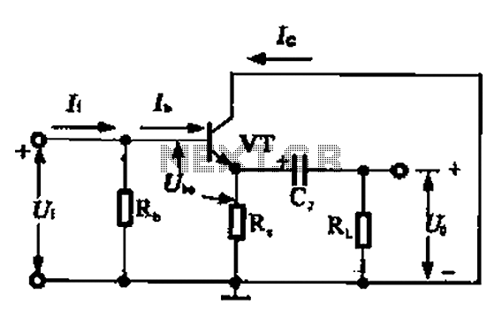
A common collector amplifier circuit can be analyzed through its DC and AC paths. The DC path provides a bias circuit for the power transistor, determining whether it is in an active or off state, primarily influenced by the...
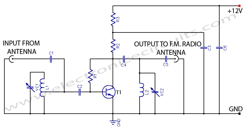
This FM booster allows for clear reception of programs from distant FM stations. The circuit features a common-emitter tuned RF preamplifier utilizing the VHF/UHF transistor 2SC2570 (only labeled as C2570 on the transistor body). The input coil L1 is...
To get a low output impedance I needed to use quite a high step-down ratio (20:1); after all, the amplifier may be used with headphones of lower impedance than the 300 Ohms of the HD600. The output valve is...
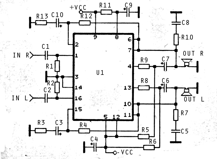
The audio amplifier circuit is highly suitable for home use, particularly with subwoofer or woofer speakers. Commonly referred to as a home amplifier, these audio amplifiers are based on integrated circuits (ICs), specifically the STK series, which includes models...
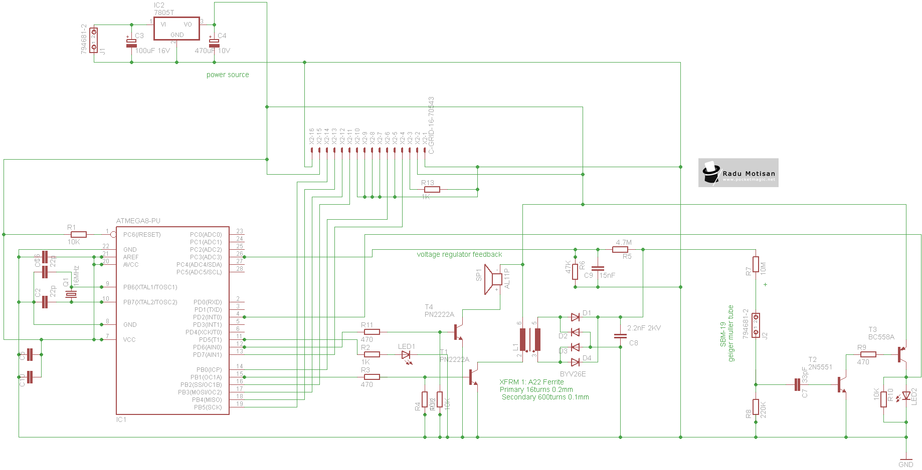
An efficient and stable construction for radiation dosimetry needs. The design centers around the Atmel Atmega8 microcontroller and a Russian Geiger Muller tube, specifically the CTC-1 tube for high gamma doses. The dosimeter is compatible with various tubes including...
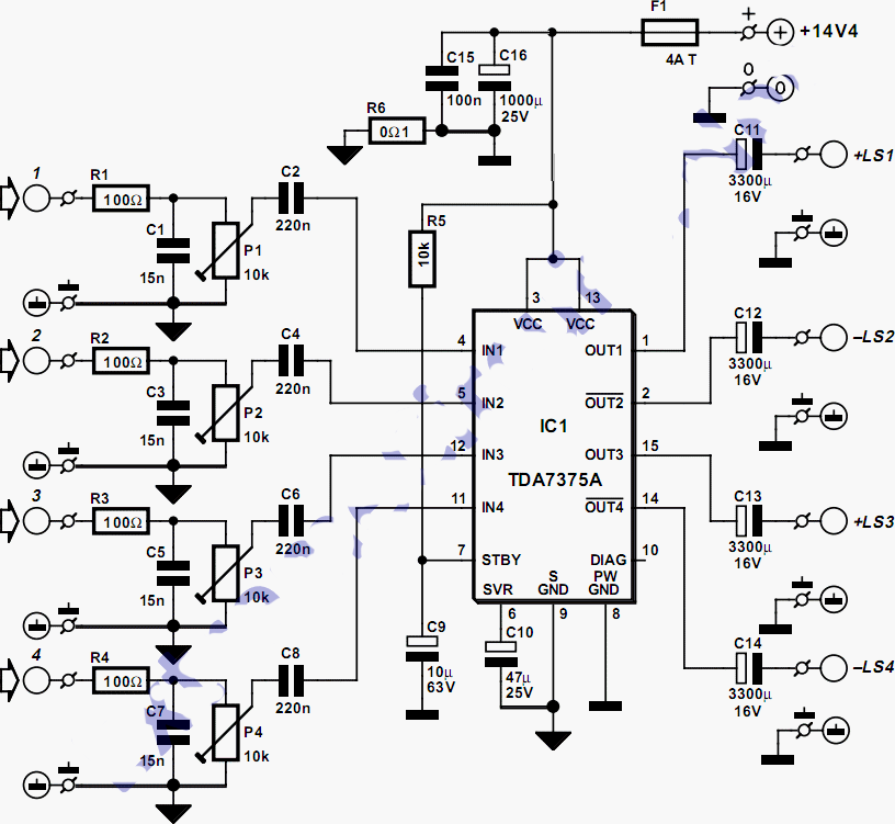
This quad amplifier is designed primarily for automotive use but can also be applied in various medium-power scenarios. The TDA7375A is suitable for situations requiring a reasonable amount of audio power with a relatively low supply voltage. It is...