
Common collector amplifier circuit DC and AC path b
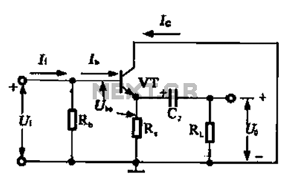
The common collector amplifier, also known as an emitter follower, is a configuration that provides voltage gain while maintaining a low output impedance. It is particularly useful for impedance matching between different stages of a circuit. The circuit comprises a bipolar junction transistor (BJT) with its collector connected to the power supply and the emitter connected to the load. The input signal is applied to the base of the transistor.
In the DC analysis, the biasing network is crucial for the proper operation of the amplifier. Typically, resistors are used to set the base voltage, ensuring that the transistor operates in the active region. The DC path allows for the establishment of a stable operating point, which is essential for linear amplification. The bias current flowing through the transistor is determined by the values of the resistors in the biasing network and the power supply voltage.
For AC analysis, the circuit's behavior is examined under small-signal conditions. The coupling capacitor, connected at the input, blocks any DC component of the signal while allowing AC signals to pass. This capacitor effectively shorts the AC signal to ground at higher frequencies, ensuring that the transistor responds only to the variations in the input signal. The output voltage follows the input voltage, minus the base-emitter voltage drop, which is typically around 0.7V for silicon transistors.
In summary, the common collector amplifier is an essential building block in analog electronics, providing efficient signal buffering and impedance transformation. Its design considerations, including biasing and coupling, are critical for achieving the desired performance in various applications. Common collector amplifier circuit DC and AC path b (3) common-collector amplifier circuit DC and AC path when common collector amplifier circuit for analysis, can be divided i nto DC and AC two paths, as shown in FIG. The DC path to provide a DC bias circuit of the circuit from the power transistor, the transistor is in an enlarged state or the off state, it is mainly determined by the bias. This circuit also provides energy for the transistor circuit. AC AC signal path is functioning circuit, a capacitor AC signal can be regarded as a short circuit, the internal resistance of the power supply also depends on the AC signal is short-circuited.
Related Circuits
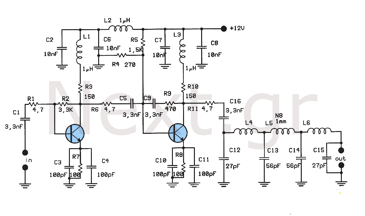
This amplifier is designed to amplify low-level signals from oscillators in the FM band. It lacks frequency regulators with variable capacitors and coils, providing a wide range and moderate power suitable for driving multiple linear amplifiers. The construction utilizes...
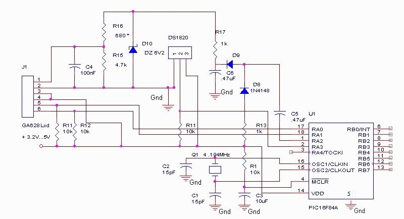
The DS18S20 digital thermometer offers a precision of 0.5 °C, with the SCRATCHPAD being read every 800 ms. Capacitors C5 and C6, along with diodes D8 and D9, form a voltage doubler to power the LCD panel. The DS18S20...
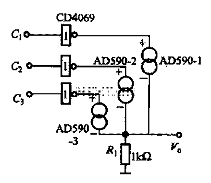
The AD590 is illustrated in a basic application circuit. As the AD590 provides a current output, a series resistance is used to convert this output current into a voltage. In the circuit, RP serves as the output voltage (vo)...

This circuit diagram is part of an RF circuit. It features an FM transmitter circuit diagram using the BH1417 integrated circuit from RHOM, which incorporates multiple functionalities in a compact design. The IC includes pre-emphasis and a limiter to...
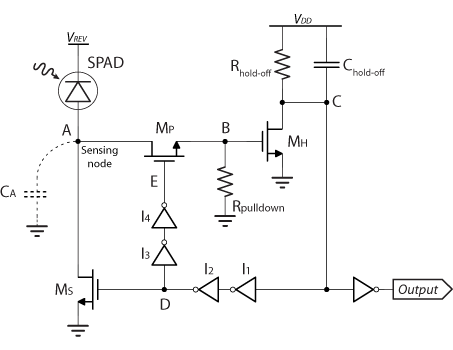
VLQC is a quenching circuit developed in the laboratory to meet the specific requirements of an array, including high compactness, cross-talk avoidance, and low afterpulsing. In the VLQC design, a single transistor is utilized to perform the sensing, quenching,...
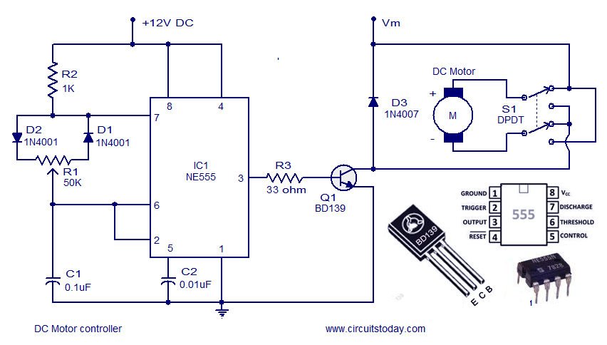
A DC motor controller based on an NE555 timer is presented here. The direction of rotation of the DC motor can also be changed using this DC motor speed control circuit. The described circuit utilizes the NE555 timer IC in...