
NTC protection circuit three-phase asynchronous motors
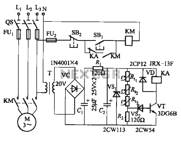
The semiconductor thermistor serves as a critical component in thermal protection applications, particularly in electrical machinery. Its sensitivity to temperature changes makes it an effective tool for monitoring and controlling the thermal environment of electrical windings, thereby preventing overheating and potential damage. The thermistor's small size allows for easy integration into compact spaces within electrical assemblies, while its reliability ensures consistent performance over time.
In practical applications, the thermistor is positioned in close proximity to the stator windings, where it can accurately measure the temperature of the wire insulation. The use of epoxy cement for securing the thermistor enhances its durability and thermal conductivity, ensuring that temperature readings are representative of the actual winding temperatures.
The choice between NTC and PTC thermistors depends on the specific application requirements. NTC thermistors exhibit a decrease in resistance with an increase in temperature, making them suitable for applications where a drop in resistance indicates a rise in temperature. Conversely, PTC thermistors increase resistance with rising temperature, providing a protective response that can be utilized in over-temperature conditions.
The accompanying circuit diagram, as referenced in Figure 4-1, illustrates the integration of the thermistor within the thermal protection system. The protection circuit is designed to respond to temperature variations by activating a switch circuit, which can be used to disconnect power or trigger alarms when predetermined temperature thresholds are exceeded. The selection of appropriate resistors (R1 and R2) is essential for calibrating the circuit's response characteristics, ensuring that the system operates effectively within the desired thermal limits.
Overall, the semiconductor thermistor is a vital component in maintaining the operational integrity of electrical systems by providing essential thermal monitoring and protection capabilities.Semiconductor thermistor embedded thermal protection element belongs, it is sensitive to temperature, temperature error of 5 . Its reliability , small size (diameter 3. Smm), easy to install, easy to embed winding, use it as a temperature sensing element can effectively reflect the electrical winding temperatures motivation. Thermistor on the three-phase stator windings, close to the wire, with epoxy cement. Thermal resistance has a negative temperature coefficient thermistor (NTC) and positive temperature coefficient thermistor (PTC) of the points.
Circuit shown in Figure 4-1. Wherein Figure 4-1 (b), (c) only one shown protection circuits, the main circuit not shown. They are a switch circuit consisting of a single tube amplifier. Thermistor brother. , R. . , R. , The choice RRC6 type or MF-15 type (lokfl, 20 ), this thermistor in about lkfl 100 when, 110 at about 0.6k, Cl.
Related Circuits
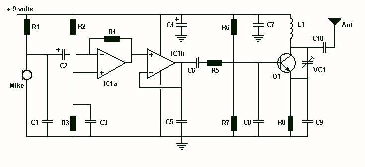
L1 is 0.112uH (this tunes to the middle of the FM band, 98 MHz, with VC1 at its centre value of 33pF). L1 is 5 turns of 22 swg enamelled copper wire close-wound on a 5mm (3/16") diameter former....
T-121 temperature sensor electronic thermometer circuit diagram shown below The T-121 temperature sensor circuit is designed to measure and display temperature readings accurately. The circuit typically consists of a temperature sensor, such as the T-121, which converts temperature variations into...
The purpose of this circuit is to animate shop windows using a capacitive sensor placed behind a postcard-like banner. The card is positioned against the glass inside the shop window, allowing visitors to activate the relay by placing their...
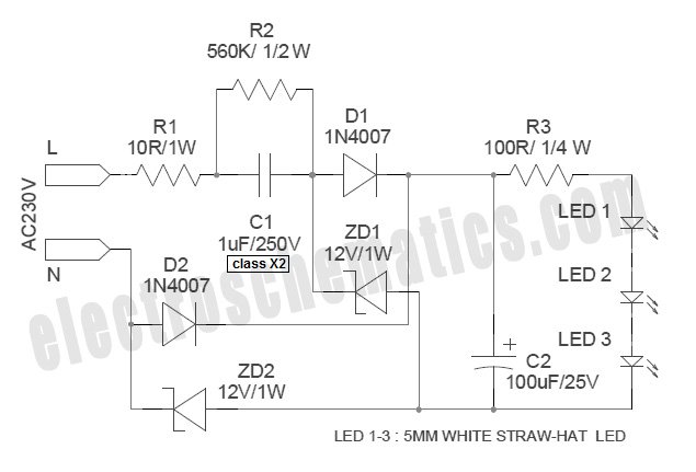
White Light Emitting Diodes (LEDs) now available can serve as a strong alternative to incandescent lamps in lighting applications. Today's White LEDs are... White Light Emitting Diodes (LEDs) represent a significant advancement in lighting technology, offering energy efficiency, longevity, and...

The Digital Combination Lock Circuit is a schematic for a simple electronic combination lock utilizing the LS7220 integrated circuit (IC). This password-protected digital lock can activate a relay to control any device by entering a preset combination of four...
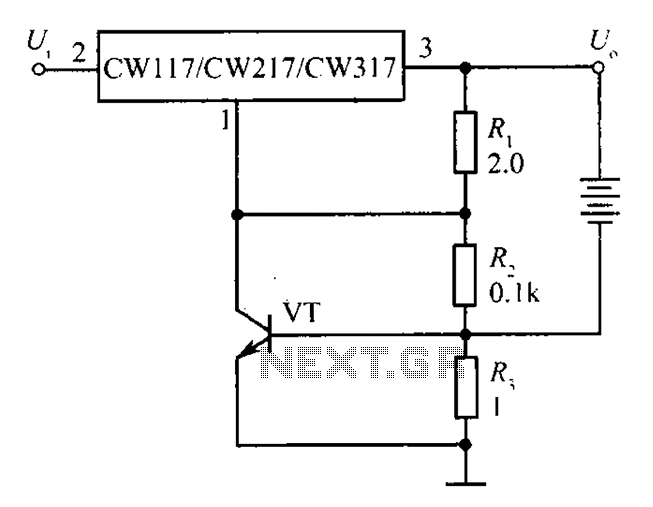
The circuit depicted in the figure is a limiting protection charger. The VT transistors and resistor R3 create a limiting network. As illustrated, resistor R3 is connected in series with the battery being charged, acting as the emitter resistor...