
OBD II Car Computer

The described circuit utilizes the OBD-II protocol to interface with a vehicle's onboard diagnostics system. The NerdKits microcontroller kit is employed to capture data transmitted over the VPW protocol, which is specific to certain General Motors vehicles. The connection to the OBD-II port is made through a series of wires that link the microcontroller to the vehicle's data bus. The microcontroller interprets the signals received, allowing for real-time monitoring of various engine parameters.
To ensure compatibility with the vehicle's electrical system, an optocoupler is integrated into the design. This component provides electrical isolation, protecting the microcontroller from voltage spikes and noise generated by the vehicle's electrical system. The optocoupler's LED is connected to the vehicle's data line, while the phototransistor side interfaces with the microcontroller, allowing it to read the incoming signals without direct electrical contact.
The power supply for the microcontroller is derived from the vehicle's battery, which requires careful management to prevent damage. A voltage regulator is used to step down the battery voltage to a level suitable for the microcontroller. Additionally, a bypass capacitor is included in the circuit to filter out any high-frequency noise, ensuring stable operation of the microcontroller during data acquisition.
Safety precautions are paramount when working with automotive electronics. The circuit design should include fuses or circuit breakers to protect against overcurrent conditions. It is also advisable to use insulated tools and wear protective gear when handling electrical components in a vehicle environment.
In summary, this project showcases the integration of a microcontroller with a vehicle’s OBD-II system using the VPW protocol. It highlights the importance of electrical isolation, proper voltage management, and safety considerations in automotive electronics projects.Using the OBD-II (On Board Diagnostics) protocol, we can read live information from a car`s computer with our NerdKits microcontroller kit, as explained by our guest star, Elena T. , MIT class of 2011. This uses the port under your steering wheel to receive all kinds of information, and is used by auto mechanics for troubleshooting the "Check Engi
ne" light, and for periodic emissions tests with onboard sensors. In this microcontroller project, we implement the Variable Pulse Width (VPW) protocol, which is generally found on General Motors cars. Please note that if you attempt this project, your car may have a different signaling protocol, which would not be compatible with our code.
The car we used was a 1997 Chevy Cavalier. This was introduced soon after the 1996 law requiring US cars to have OBD-II buses, but there are not many sensors accessible from the data bus. On newer cars, you`d find oxygen sensors (allowing you to calculate MPG), but for our demo, we were able to measure: WARNING: Please note that by attempting this project, there are several risks to yourself and your property.
This project involves working in the presence of car battery voltage, which can supply dangerous amounts of current and cause fire or electrical damage. This project involves working with your car computer, and while manufacturers do their best to make them robust, it is possible to irreversibly damage your car`s computer or the vehicle itself.
And of course, if you`re the driver, you should be focusing on the road, and not some circuit and LCD on your dashboard. Optocouplers (or opto-isolators) provide a way to transmit information without creating a direct electrical connection.
In a single small chip package, they have an LED and phototransistor. Current passed through the LED side of the chip makes light, which hits the base of the phototransistor and allows current to flow through the collector to emitter. This may seem unnessary, but it is useful for a few reasons: Level shifting. The car`s battery voltage will be about 12-14V, and in order to pull the data bus high as the protocol requires, we need some way to trigger a transistor at this level.
Optical isolation means we don`t have to worry about the relative levels of our voltages, which would be a challenge here. Electrical isolation. The car`s battery voltage will be noisy thanks to an alternator that`s operating at variable RPM, a huge spike of current every time a cylinder needs to fire its spark plug, etc.
By optically coupling, we make it harder for electrical noise to disrupt our microcontroller`s proper operation. However, we found that it was fine to draw power directly from the car to power the NerdKit. To do this, we connected the car ground to our circuit ground, and the car battery voltage to the input of the voltage regulator.
We also added an extra large bypass capacitor (4. 7uF) to smooth the ripple on this supply and guarantee proper operation. You can download the source code here. Please note that the VPW protocol is a particularly "messy" one to implement, and that much of the source code here would not be applicable to a project with a different signaling protocol. This is a fairly advanced example of microcontroller programming. 🔗 External reference
Related Circuits
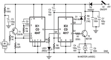
The following circuit illustrates an Infrared Toy Car Motor Controller Circuit Diagram. This circuit is based on the 4017 IC. Features: operating at .. The Infrared Toy Car Motor Controller Circuit utilizes a 4017 Decade Counter IC, which is integral...
A useful operation for the cars is delayed extinguishing internal lighting cabin of passengers, after close some door of car. Certain cars allocate this operation from their constructor. Oldest sure do not allocate such operation. This delay makes this...
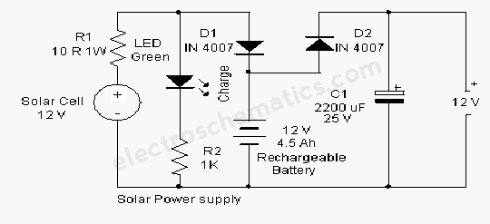
A solar-powered flasher designed to deter nocturnal animals such as bats and cats from agricultural areas or residential premises. The device emits brilliant multicolored flashes that confuse these animals, encouraging them to avoid the area. It operates automatically, activating...
Disconnecting the alarm system from the horn relay will eliminate the horn's sound during an actual alarm. This circuit silences the arming beep while maintaining the alarm by introducing a small delay into the signal. It is positioned between...
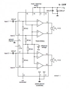
A 2x22 W car audio amplifier circuit utilizes the TDA1558, a monolithic integrated class-B output power amplifier that includes four 11 W single-ended amplifiers or two 22 W bridge-tied load (BTL) amplifiers. The TDA1558 is designed to drive speakers in...

The 2SA130 transistor is used in an oscillator circuit with an oscillation frequency of 7 MHz. The power supply voltage is 6V, and the load is a frequency-selective resonant circuit with a quality factor of 600. The circuit utilizes the...