
Infrared Toy Car Motor ControllerCircuit Based On The 4017IC
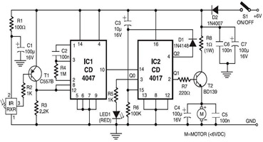
The Infrared Toy Car Motor Controller Circuit utilizes a 4017 Decade Counter IC, which is integral in controlling the operation of the toy car's motors based on infrared signals. The circuit is designed to interpret signals received from an infrared remote control, enabling the toy car to move forward, backward, or turn based on the commands sent from the remote.
The circuit typically includes an infrared receiver module connected to the input of the 4017 IC. When the infrared signals are detected, the 4017 IC counts the pulses and activates the output pins in sequence. Each output pin corresponds to a specific action for the toy car, such as moving forward or turning. The outputs of the 4017 are connected to motor driver circuits, which can handle the higher current requirements of the motors.
Additional components in the circuit may include resistors for current limiting, capacitors for noise filtering, and diodes for protection against back EMF generated by the motors. The design should ensure that the power supply is adequate for the motors, typically requiring a separate battery pack to prevent voltage drops that could affect the performance of the infrared receiver.
Overall, this circuit exemplifies a simple yet effective method to control a toy car's movements using infrared technology, leveraging the capabilities of the 4017 IC for sequential output control.The following circuit shows about Infrared Toy Car Motor Controller Circuit Diagram. This circuit based on the 4017IC. Features: operating at .. 🔗 External reference
Related Circuits
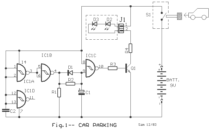
A simple but useful circuit for all who have problems with parking a car in spaces without good visibility. The electric circuit appears in picture 1. It is constituted by the IC1 and components around it. When the car...
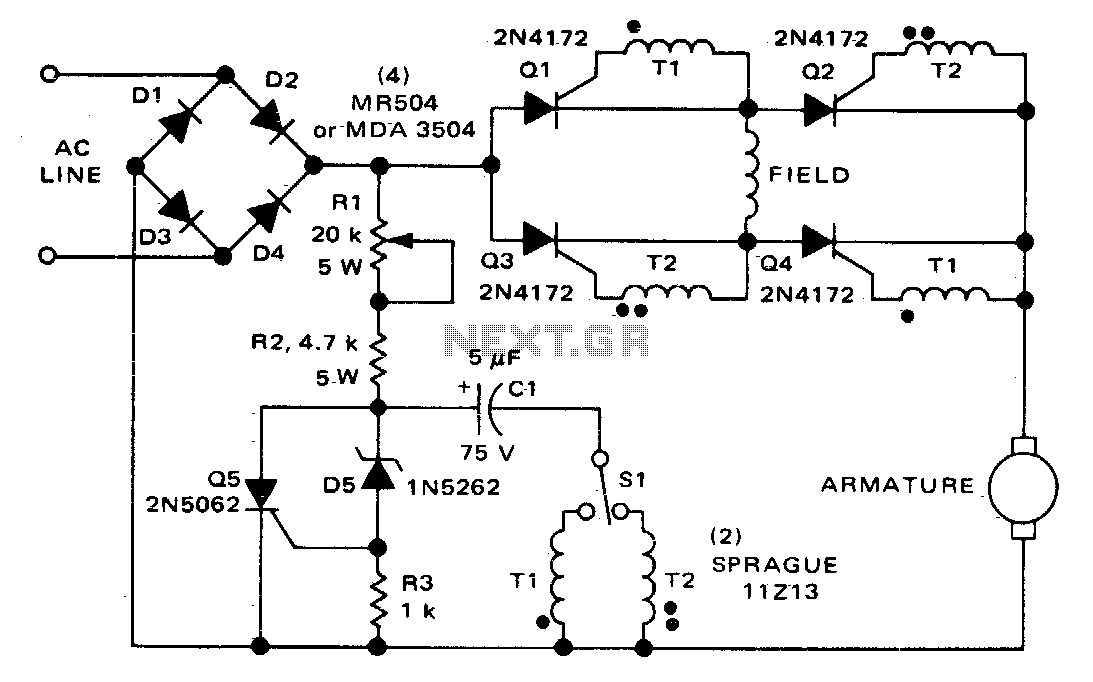
The circuit can control the speed and direction of rotation of a series-wound DC motor. Silicon controlled rectifiers Q1-Q4 are arranged in a bridge configuration and are triggered in diagonal pairs. The selection of which pair to activate is...
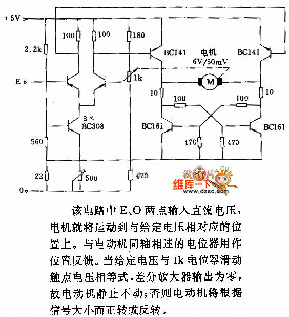
In the circuit, when E and O are input DC voltages, the motor moves to a position corresponding to the voltage. A potentiometer, coaxially connected to the motor, is used for position feedback. When the given voltage equals the...
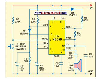
This circuit activates the car horn when the vehicle is in reverse gear. It utilizes a dual timer NE556 to generate the necessary signals. The described circuit employs a dual timer IC, specifically the NE556, which is a versatile component...

The circuit is a high-power car audio amplifier schematic. It functions as a car audio amplifier using the PA02 and LH0101 integrated circuits (ICs). Each IC delivers an output power of 30W with an 8-ohm impedance. The part list...
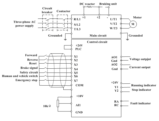
Motor control, energy efficiency of inverter (AC drive) selection, and parameters setting guidance in the mining industry: vector control, open loop or closed loop control, with energy braking unit or energy feedback unit. In the context of motor control for...
Warning: include(partials/cookie-banner.php): Failed to open stream: Permission denied in /var/www/html/nextgr/view-circuit.php on line 713
Warning: include(): Failed opening 'partials/cookie-banner.php' for inclusion (include_path='.:/usr/share/php') in /var/www/html/nextgr/view-circuit.php on line 713