
off infrared remote control schematic
The 74HC74 is a dual D-type flip-flop that operates with a supply voltage range of 2V to 6V, making it versatile for various digital logic applications. Pins 7 and 14 are critical as they correspond to the ground and Vcc (supply voltage) connections, respectively. The flip-flop can be used in applications such as data storage, frequency division, and pulse generation. The output state of the flip-flops changes on the rising edge of the clock input, allowing for synchronous operation.
The MOC3041 is an optocoupler designed for AC applications, featuring a phototransistor output that is isolated from the input side. This component is beneficial for interfacing between high-voltage AC circuits and low-voltage control circuits, providing safety and signal integrity. The internal LED of the MOC3041 is activated by the AC input, which in turn triggers the phototransistor to conduct, allowing for signal transfer without direct electrical connection.
The specified zener diode, 1N5352, is a 15V, 4W device that serves to regulate voltage in the circuit. It maintains a stable output voltage by allowing current to flow in the reverse direction when the voltage exceeds its breakdown voltage. This characteristic makes it suitable for protecting sensitive components from voltage spikes and ensuring stable operation within the specified voltage range.
In conclusion, the combination of the 74HC74 flip-flop, MOC3041 optocoupler, and the 1N5352 zener diode provides a robust solution for digital logic applications, AC signal isolation, and voltage regulation, respectively. Each component plays a crucial role in ensuring the reliability and functionality of the overall circuit design.As per the note on the schematic IC-2 is a 74HC74 TTL chip, look up the data sheet and it will show you what pins 7 and 14 are. The note for IC-3 is down lower its an AC optocoupler part number MOC3041. D2 is noted as a 15volt. 4 watt zener diode, a part number 1N5352 will work. 🔗 External reference
Related Circuits
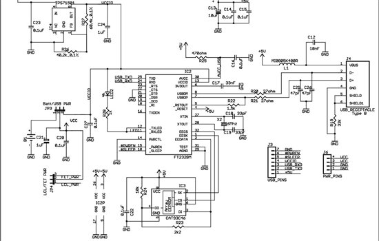
As found in SLAA458, the revised pulse oximeter application, an image of the USB schematic is attached, which is used to output collected data. There are a few questions regarding this schematic: 1) What do J3 and J6 correspond...
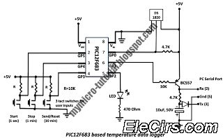
A data logger is a device that records measurements over time. The measurements could be any physical variable like temperature, pressure, voltage, humidity, etc. This project describes how to build a mini logger that records surrounding temperature. A data logger...
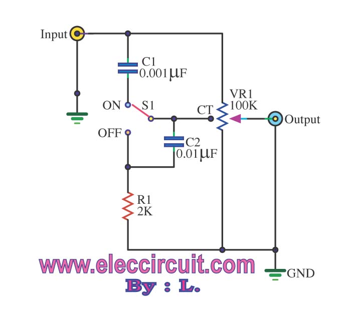
The passive tone control circuit is designed to adjust the bass without expansion, utilizing resistors (R) and capacitors (C). It functions as a frequency filter and is easy to construct, requiring no external power supply. This circuit can be...
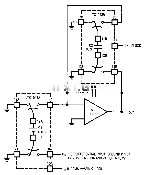
The circuit utilizes the LTC1043 in a variable gain amplifier configuration, which offers continuously adjustable gain, gain stability of 20 ppm/°C, and supports both single-ended and differential inputs. Two separate LTC1043 devices are employed in the design. The LTC1043B...

Efforts were made to minimize the number of wire jumpers on this board, but space constraints arose due to the integration of the microcontroller and motor driver on a single board. The design would have been cleaner without the...
The 555 IC is configured in an astable mode, producing a frequency that remains constant and is independent of the duty cycle. The total resistance (Rcharge + Rdischarge, considering the diode) is fixed at 22 kΩ, yielding a frequency...