
Simple DC motor PWN speed controls
The circuit utilizes a 555 timer IC configured in an astable mode to generate a square wave output. This configuration allows for continuous oscillation, producing a repetitive signal ideal for driving motors or other inductive loads. The frequency of the output signal is determined by the resistances and capacitance in the circuit. The resistors Rcharge and Rdischarge set the charge and discharge times of the timing capacitor, respectively, while the diode ensures that the capacitor charges through the intended path, preventing interference from other components.
The choice of components, particularly the MOSFET or bipolar transistor, is critical as it must handle the maximum current required by the motor. The snubber diode serves to protect the switching device from voltage spikes generated when the motor is turned off, which can otherwise damage sensitive components. Additionally, the use of a heatsink is essential for thermal management, especially when operating under high load conditions.
The inclusion of a series resistor with the snubber diode can be a strategic decision to enhance efficiency by reducing the current flowing through the diode during the off cycle, thus minimizing energy loss. However, it is crucial to balance this with the need for adequate deceleration of the motor, as a higher resistance may lead to increased inertia.
Overall, careful consideration of component ratings, configurations, and thermal management strategies is essential for the successful implementation of this circuit, ensuring reliable operation while maximizing performance and efficiency.The 555 Ic is wired as an astable and the frequency is constant and independent of the duty cycle, as the total resistance (R charge + R discharge, notice the diode) is constant and equal to 22Kohm (givin a frequency of about 1Khz, notice the hum). When the potentiomenter is all up, the Rcharge resistance is 1, 0 Kohm (the diode prevents the capaci
tor to charge through the second potentiometer section and the other 1, 0 Kohm resistor), and Rdischarge is 21 Kohm, giving a 5% on duty cycle and a 1Khz frequency. When the potentiomenter is all down, the Rcharge resistance is 21, 0 Kohm (the diode prevents the capacitor to charge through the second potentiometer section and the other 1, 0 Kohm resistor), and Rdischarge is 1 Kohm, giving a 95% on duty cycle and a 1Khz frequency.
When the potentiomenter is at 50%, the Rcharge resistance is 11, 0 Kohm (the diode prevents the capacitor to charge through the second potentiometer section and the other 1, 0 Kohm resistor), and Rdischarge is 11 Kohm, giving a 50% on duty cycle and a 1Khz frequency. If you are disgusted by the 1Khz hum of the motor try to rise the frequency out of the audible range (replacing the potenziometer), but rembember that at higher frequency inductive reactance of motor rises so the the efficiency would drop.
Obviously the mosfet (or bipolar) must have enough current capability to drive the motor, so the drain (or collector) current must be equal to maximum motor current (at power supply voltage, when it is blocked). The snubber diode too, because it shorts the motor on the off cycle. Both mosfet (or bipolar) and diode have to be hooked (if you don`t want them cooked ;-) ) to a heatsink if the max motor current is more than 100 or 200mA.
I suggest to not stress to much the motor with too much work because it overheats both motor, transistor and diode. If you don`t want braking in the off cycle just place a resistor in series with the snubber diode, it should rise a bit efficiency but have more inertia when slowing the motor down.
The value of the resistor must be R=V(breakdown transistor) / Imax, and the power should be 5W. Mosfets have internal zener diode, but don`t count on it ;-) 🔗 External reference
Related Circuits
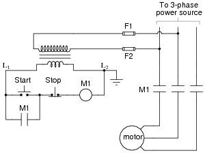
The most challenging aspect of interpreting ladder diagrams, particularly for individuals familiar with electronic schematic diagrams, is the representation of electromechanical relays. The operation of a motor control circuit should be explained, detailing what occurs when the "Run" switch...
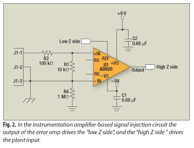
A signal-injection circuit for control-loop analysis is flat from DC to 200 kHz, isolated from chassis ground, and easily constructed with a readily available instrumentation amplifier. The signal-injection circuit is designed to facilitate control-loop analysis by providing a stable and...
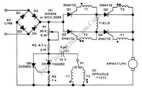
This is a motor controller circuit that controls the speed and direction of series-wound motors. This circuit employs silicon controlled rectifiers (SCR). The motor controller circuit is designed to manage both the speed and direction of series-wound motors, which are...
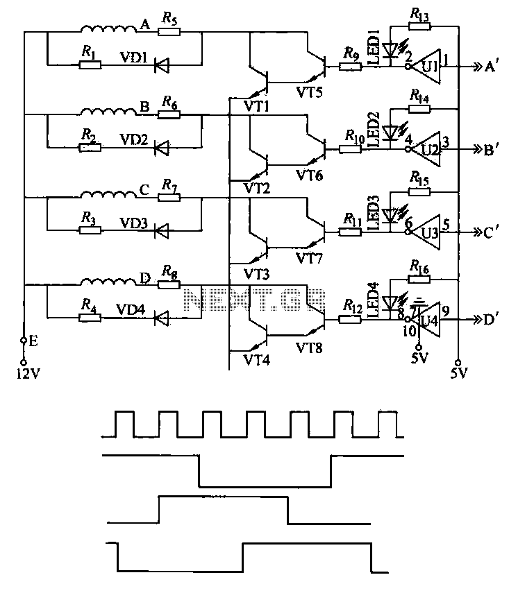
This machine utilizes the FD-CAS-923 1-stepper motor control experiment board with a 4-phase stepper motor to avoid its schematic shown in Figure 4-42a. The JK1 cop 40 core flat cable connector allows for signal arrangements compatible with EICE51 simulation...
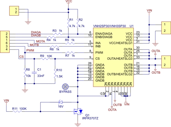
Need more current? If you have a larger motor ready for use, the Pololu High Current Motor Driver Board 14A 6V-16V is the ideal solution. Connect three digital lines to your microcontroller (five if error condition feedback is desired),...
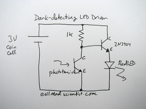
How can an LED be activated in low light conditions? This scenario, often referred to as the "nightlight problem," is applicable in various situations such as emergency lights, street lights, and even computer keyboard backlights. There are numerous solutions...