
Ohm Meter For Low Resistence measurement
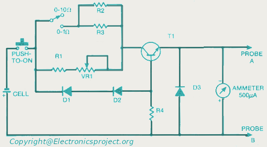
The ohmmeter circuit is primarily used to measure the resistance of low-value resistors, typically in the range of milliohms to a few ohms. The basic operation of an ohmmeter involves applying a known voltage across the resistor under test and measuring the resulting current flow. Ohm's law (V = I × R) is then used to calculate the resistance value.
In a typical low-resistance ohmmeter circuit, a precision voltage source is employed to ensure accurate measurements. This voltage source can be a battery or a regulated power supply. A shunt resistor is often included in the circuit to provide a reference point for the current measurement. The current flowing through the resistor under test is measured using a sensitive ammeter or a microcontroller with an analog-to-digital converter (ADC) for digital readouts.
The circuit may also incorporate a display unit to show the measured resistance value. This can be an analog meter or a digital display, depending on the design requirements. Additionally, to enhance accuracy, the circuit can be designed with temperature compensation features, as resistance values can vary with temperature changes.
For low-resistance measurements, it is crucial to minimize the impact of lead resistance. This can be achieved by using four-wire (Kelvin) measurement techniques, where separate pairs of leads are used for supplying current and measuring voltage across the resistor. This method effectively eliminates the resistance of the test leads from the measurement, providing more accurate results.
Overall, the design of a low-resistance ohmmeter circuit requires careful consideration of component selection, circuit layout, and calibration procedures to ensure precise and reliable measurements.Here you can get the circuit diagram of ohm meter for a low resistor measurement. More about you can find 300+ electronics circuit in this site 🔗 External reference
Related Circuits
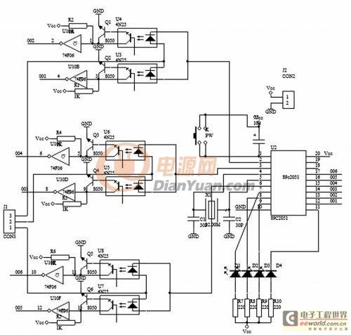
In electronic technology, the triode utilizes a variety of general components and parts. The parameters of the triode and numerous electrical parametric measurement schemes are closely related to measurement results. Therefore, in electronic design, the base pin, typological judgment,...
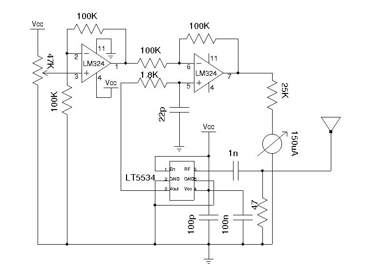
A field strength meter is highly beneficial when dealing with RF devices. It allows for the rapid diagnosis of transmitter circuit functionality and can detect RF signals present in the environment. The simplest form of a field strength meter...
The Car shows the distance a train travels on a 5 digit LCD display. The distance is indicated down to 1/100th of a mile (about the length of a 50 foot car) with an accuracy of approximately plus 2...
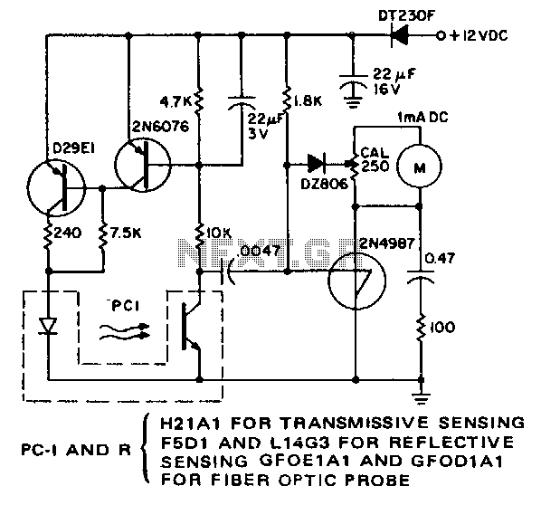
The purpose of this simple circuit is to enable remote, non-contact measurement of the speed of rotating objects. The circuit exhibits high linearity and accuracy, typically constrained by the milliammeter utilized and the initial calibration process. It is configured...
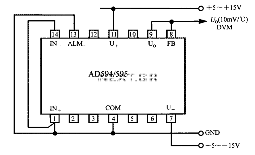
The AD594/595 can be configured to measure temperature in Celsius. In the circuit diagram, the IN+ and IN- terminals should be shorted to the COM terminal. The output voltage (Uo) has a temperature coefficient of 10 mV/°C, which can...
A meter is a measuring instrument. An ammeter measures current, a voltmeter measures the potential difference (voltage) between two points, and an ohmmeter measures resistance. A multimeter combines these functions, and possibly some additional ones, into a single instrument....