
Wideband RF Field Strength Meter
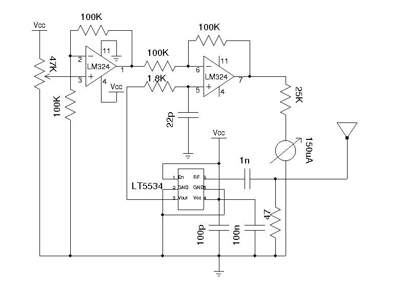
A field strength meter typically consists of three main components: an LC circuit, a detector, and a display element. The LC circuit, which is composed of an inductor (L) and a capacitor (C), is tuned to resonate at a specific frequency, allowing it to effectively respond to RF signals within that frequency range. The quality factor (Q) of the LC circuit is crucial as it determines the selectivity and sensitivity of the meter.
The germanium diode serves as a detector, converting the RF signal into a DC voltage proportional to the signal strength. The choice of a germanium diode is significant due to its low forward voltage drop and high sensitivity to weak signals, making it ideal for RF applications. The output from the diode is then fed into a high-sensitivity current meter, which provides a visual representation of the signal strength detected by the LC circuit.
In practical applications, the field strength meter can be used for tasks such as aligning antennas, troubleshooting RF circuits, and measuring signal levels in various environments. However, it is essential to note that while this simple design is effective for low-frequency RF applications, its performance may be limited at higher frequencies, where more sophisticated designs may be required to achieve accurate measurements and better sensitivity.
Additional enhancements can include the integration of an adjustable tuning mechanism for the LC circuit, allowing the user to select the desired frequency range more effectively. Furthermore, incorporating a logarithmic amplifier can improve the dynamic range of the meter, enabling it to measure a broader spectrum of signal strengths without saturation. Advanced field strength meters may also feature digital displays and microcontroller-based signal processing for enhanced functionality and ease of use.Field strength meter is extremely useful when working with RF devices. It can be used to quickly diagnose whether a transmitter circuit is working, and can be used to detect RF signals in the environment. The simplest field strength meter could be built with a tuned LC circuit and a germanium diode, just like the way of a building a crystal radio except replacing the ear piece with a high sensitivity current meter.
While this approach fits the needs of most simple applications, it has a pretty n. 🔗 External reference
Related Circuits
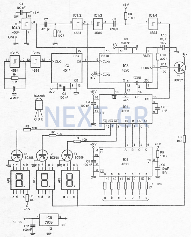
This compact device, designed primarily for modelers, provides instantaneous readings of pulse duration in milliseconds (ms). It can measure servomotor positions, typically ranging from 1 ms to 2 ms, and can also perform repetitive or non-pulsed measurements, such as...
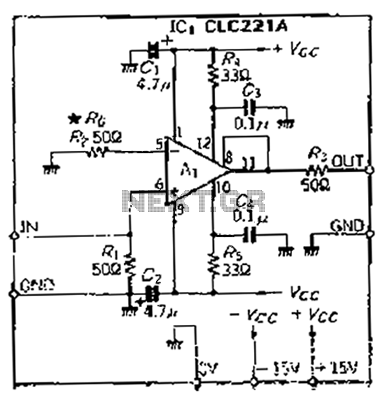
The CLC221A is designed with a traditional operational amplifier (OP) configuration. It is a high-performance current-feedback amplifier capable of operating in both non-inverting and inverting modes. The amplifier features a flat-rate characteristic, which is particularly effective when configured in...
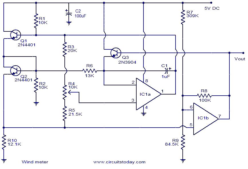
This is a simple wind meter (anemometer) circuit. While accuracy cannot be guaranteed, the circuit functions adequately. It can measure wind speeds up to 75 m/s. Transistors Q1 and Q2 are employed for wind sensing, utilizing the relationship between...
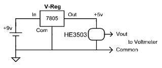
Have you ever wanted to determine the strength of a magnet, observe how the magnetic field strength changes with distance or temperature, or evaluate the effectiveness of a shield placed in front of the magnet? Voltmeters are relatively inexpensive...
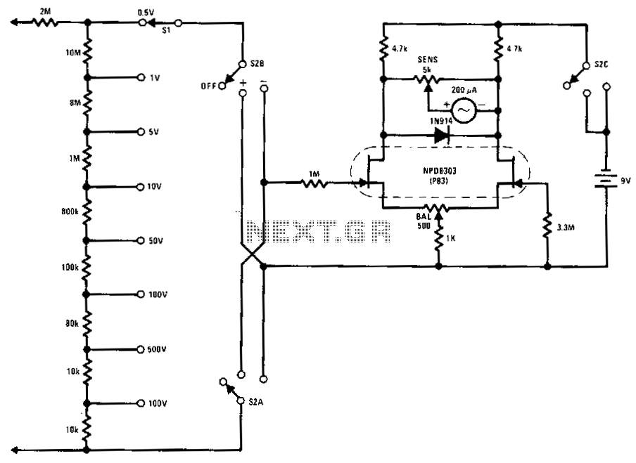
This FETVM replaces the function of the VTVM and eliminates the need for a standard line cord. Additionally, FET drift rates are significantly better than those of vacuum tube circuits, enabling a full-scale range of 0.5 V, which is...
This document outlines the procedure for creating a simple RPM meter using the AVR ATmega8 microcontroller. The RPM meter designed will operate in a contactless manner. The RPM meter circuit utilizes the AVR ATmega8 microcontroller, which is a popular 8-bit...