
LA3161 based Preamplifier circuit with explanation

The LA 3161 preamplifier is designed to efficiently process low-level audio signals while providing high fidelity and low distortion. With its dual low-noise architecture, it is particularly suitable for stereo audio applications, ensuring that both channels maintain a consistent quality of sound reproduction. The high input resistance of 1MΩ minimizes the loading effect on the signal source, allowing for accurate signal amplification without significant attenuation.
The output resistance of 10kΩ is optimal for interfacing with subsequent stages in an audio system, such as power amplifiers or analog signal processing units. The open-loop gain of 78dB indicates a strong amplification capability, which is beneficial for enhancing weak audio signals to a usable level. The internal voltage regulator ensures stable operation across varying supply voltages, enhancing reliability in diverse applications.
The pin configuration of the LA 3161 is straightforward, facilitating easy integration into existing designs. Pins 1 and 8 serve as the differential inputs, allowing for balanced audio signals, while pins 3 and 6 provide the amplified output. The feedback mechanism at pins 2 and 7 is crucial for maintaining stability and controlling the gain of the amplifier, ensuring that the output remains linear and free from distortion.
In terms of construction, the availability of ready-made PCBs simplifies the implementation process, making it accessible for both professional and amateur audio engineers. For custom builds, using a Veroboard allows for flexibility in design but requires careful attention to grounding practices to prevent issues such as ground loops and oscillations, which can degrade audio performance.
Overall, the LA 3161 preamplifier is a robust solution for audio amplification needs, providing high-quality performance in a compact and user-friendly package. Its design features and operational characteristics make it a valuable component in both consumer and professional audio systems.Preamplifiers are used to amplify low level signals such as those from mikes, tape heads before they are fed into power amplifiers. Power amplifiers are generally less sensitive. Frequency response also can be suitably trimmed and modified at preamp stage. LA 3161 is one of those widely used in tape decks and amplifiers as a stereo preamplifier. B lock Diagram is shown in Figure. LA 3161 has two low noise preamplifiers with good ripple rejection on chip catering to stereo applications. External part count is low and Single In line (SIL)(Figure 43) package makes mounting easy. Wltile the operating voltage is 9V, the IC can tolerate voltages up to 18V. Typical input resistance is WOK and output resistance is 10K with an open loop gain of78dB. Block diagram of the IC is given below. Input is given at Pin 1 and 8, output is taken at Pin 3 and 6, and negative Feedback is given at Pin 2 and 7.
Power is at Pin 5 and Pin 4 is the ground terminal. There is an internal voltage regulator. Ready made PCBs, even populated PCBs are available using this very useful IC. You can still build one, with a Veroboard provided proper care is taken about the ground returns. It simply means that one should not connect ground terminals of output and input at the same place. This will create serious oscillations and normal hobbyist will be left in the woods. Please read general instructions for working with amplifiers in the end. 🔗 External reference
Related Circuits
A 12V battery charging circuit is presented, featuring a straightforward diagram for a rectifier. The lead-acid trickle charger circuit is detailed along with its rectifier. The 12V battery charging circuit is designed to charge lead-acid batteries using a trickle charging...
This is a simple and cost-effective inverter designed to power a small soldering iron (25W, 35W, etc.) when a mains supply is not available. The circuit utilizes eight transistors along with several resistors and capacitors. Transistors Q1 and Q2,...
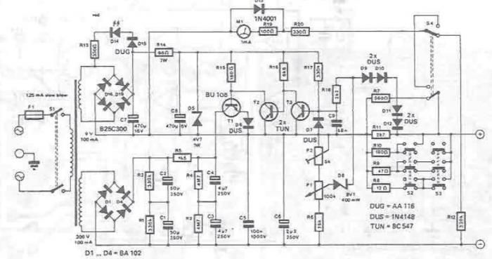
A DC power supply can be designed using high voltage transistors to provide an adjustable supply voltage ranging from 10 to 300 volts, which can be modified with potentiometer P1. Transformers used in these power supplies typically feature multiple...
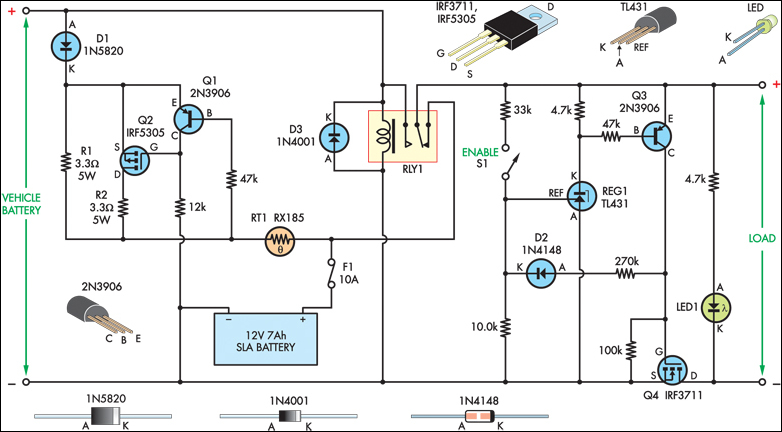
The SLA battery is charged from the vehicle's battery. When the engine is running, the voltage remains fairly constant, which greatly simplifies the charging circuit. If the SLA battery is fully charged, any further charging current from the vehicle...
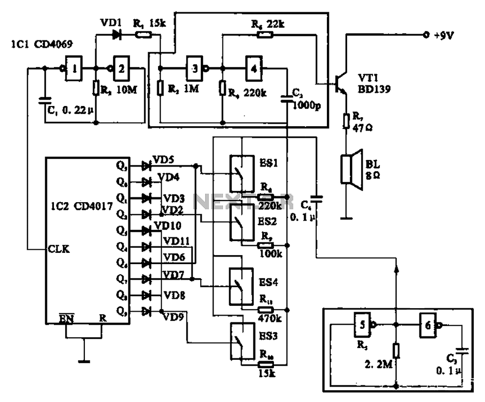
The circuit illustrated is an analog signal generator designed to produce a chirping sound, simulating birds singing. It employs six CD4069 inverters to create three oscillators, with two of them functioning as ultra-low frequency oscillators. The oscillation frequency is...
A Variable DC Power Supply is an essential tool for electronics hobbyists. This circuit is not entirely new, but it is simple, reliable, robust, and short-proof, offering variable voltage up to 24V and variable current limiting up to 2A....