
One circuit thermistor relay contacts to prevent competition

In this circuit design, the implementation of a negative temperature coefficient (NTC) thermistor serves as a crucial component for managing relay contact competition in contactor control systems. The NTC thermistor exhibits a high resistance at ambient temperatures, which allows for a gradual increase in current demand without immediate activation of the relay. This characteristic is essential for preventing simultaneous engagement of multiple relay contacts, which can lead to circuit instability or damage.
The operational sequence begins when power is applied to the circuit. Initially, the NTC thermistor maintains a high resistance, limiting the current flow to the downstream components. This delay period, typically set at around 0.5 seconds, is intentionally designed to allow the system to stabilize before any relay activation occurs. During this time, the thermistor's resistance begins to drop significantly as it heats up due to the flowing current.
Once the resistance of the NTC thermistor decreases sufficiently, it allows a higher current to flow through the circuit, activating the time delay relay (KA). This relay then engages the contactor (KM) to control the load. The precise timing of this activation is critical, as it ensures that the contactor is engaged only after the initial surge of current has passed, thus preventing any potential competition among the relay contacts.
The design also incorporates protective measures to ensure that the circuit remains stable and responsive under varying load conditions. By carefully selecting the specifications of the NTC thermistor and the time delay relay, the system can be tailored to meet specific operational requirements. Overall, this approach enhances the reliability and efficiency of contactor control systems by minimizing the risk of contact competition and ensuring smooth operation.Competition is ~ relay contacts contactor control systems often encounter problems, too much trouble to deal with, and sometimes need to add a lot of elements to add. However, if the use of negative temperature coefficient thermistor (NTC) delay switching characteristics, can easily and effectively prevent relay contact competition. Circuit 11 in FIG. 6. It is the thermistor resistance RT larger at room temperature, through the current demand after a period of delay (about 0. 5s), the sharp decline in the resistance, time delay relay KAz pull to avoid contact with the contactor KM point competition dispute, avoid circuit out of control.
Related Circuits
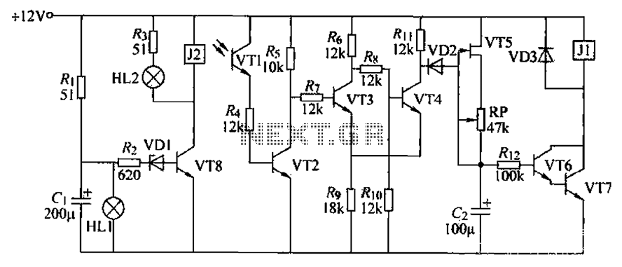
A blocking material monitoring circuit is presented. When the optical path is obstructed by the material, the phototransistor VT1 turns off, which subsequently turns off transistors VT2, VT3, and VT4. This arrangement is coupled to a flip-flop configuration. When...
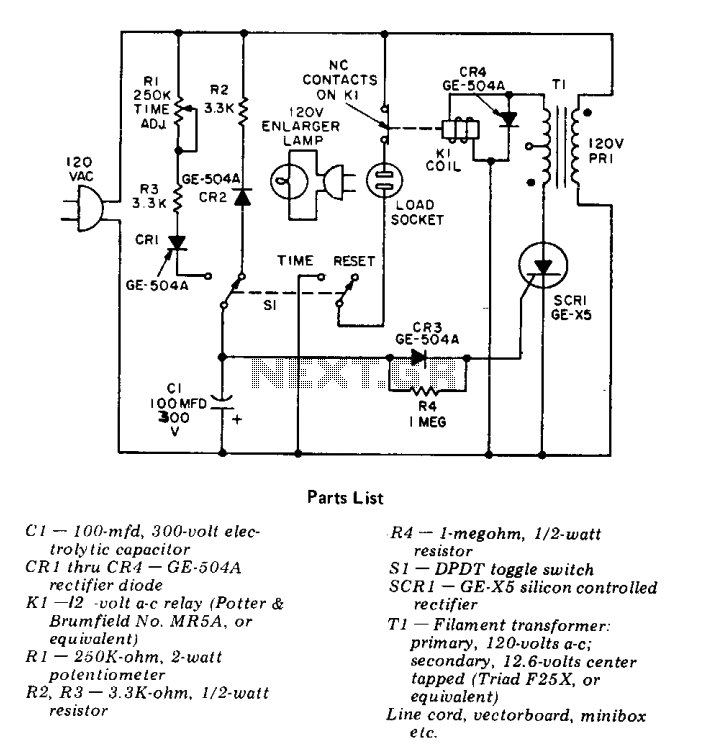
This precision solid-state time delay circuit features both delayed off and delayed on switch functions, which can be interchanged by simply swapping the relay contacts. The described time delay circuit is designed to provide precise control over the timing of...
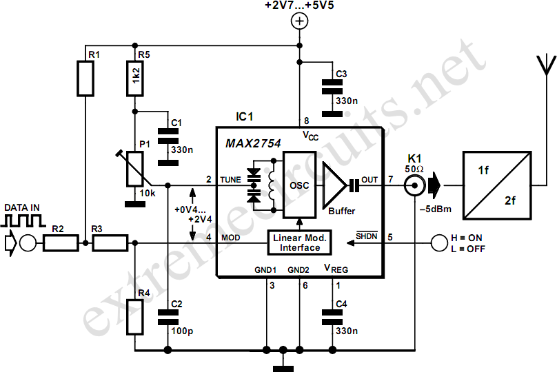
High-frequency voltage-controlled oscillators (VCOs) are challenging to construct, which is why Maxim has developed the integrated 1.2 GHz oscillator, the MAX2754. The center frequency is adjustable via the TUNE input, while a linear modulation input allows for frequency modulation....

This circuit for an intercom is a stand-alone electronic communications system designed for limited or private dialogue. The schematic illustrates the application circuit of the LM390 in the intercom configuration. Gain control can be achieved by capacitively coupling a...
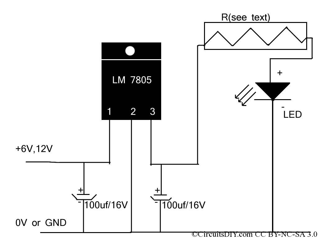
If the reader arrived here via Google, they may have encountered other circuits for high-power LED driving that include many components such as inductors, operational amplifiers, various regulator ICs, transistor feedback networks, and microcontrollers. While those circuits tend to...
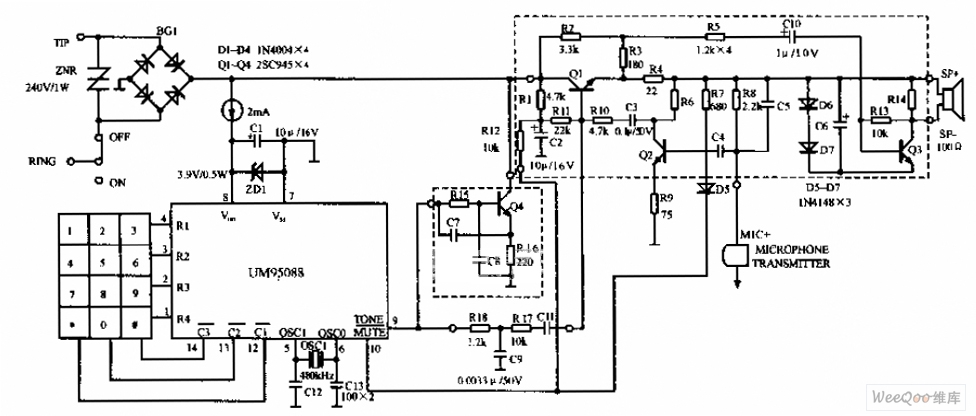
The UM95088 telephone circuit diagram is depicted in the image above. The UM95088 is a specialized integrated module designed for dual-tone multi-frequency (DTMF) telephone dialing. It utilizes CMOS technology and comes in a 14-pin dual-in-line package. The schematic for...