
One of capacitive sensing oscillator circuit burglar alarm

The circuit described operates as a proximity sensor using a combination of a 555 timer IC and an operational amplifier. The 555 timer is configured in a monostable mode, where it generates a pulse when a change in capacitance is detected. The metal plate serves as a sensing element; when an object approaches, the capacitance between the plate and ground increases. This change is reflected in the timing characteristics of the 555 timer, which is influenced by the RC time constant determined by the resistors and capacitors in the circuit.
The CA3130 operational amplifier is employed to compare the output of the RC network with a reference voltage, providing a means to detect the change in capacitance. The output of the operational amplifier drives the transistor VT, which acts as a switch to control the relay KA. When the relay is activated, it can be used to trigger an external alarm system or indicator.
The adjustable potentiometers RPi and RP2 allow for fine-tuning of the sensitivity of the sensor, enabling the user to set the threshold at which the circuit will react to the presence of an object. This feature is particularly useful in applications where varying distances or object sizes need to be accounted for.
Overall, this circuit provides a robust solution for proximity detection, leveraging the properties of capacitors and the functionality of operational amplifiers and transistors to create a responsive and adjustable alarm system. By the 555 IC Ai, capacitors Cl, Cz and metal plate (tablet) M distributed capacitance Co and resistor Ri to ground, R2 consisting self-excited multivibrator; the R3-Rs and C3 ~ C5 composition three -order RC integration network; by the CA3130 operational amplifier Az, Re, R7 and RPi, RPz composition comparator; by the transistor VT and R8, R9 composition amplifier. When the body close to the metal plate M, Co capacitance increases, the multivibrator oscillation frequency decreases, RC network outputs a negative pulse, VT conduction, the relay KA pull, turn alarm, an alarm signal.
Adjustment potentiometer RPi, RP2, can change the sensitivity of the device.
Related Circuits
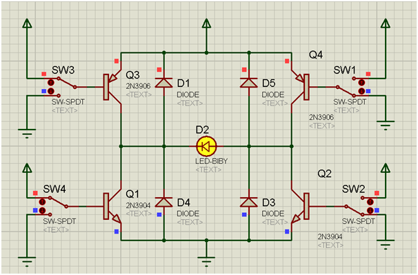
An H-bridge is a circuit configuration that enables the application of voltages in both directions. It permits higher voltage and current to be applied to the load while controlling the direction using a low voltage signal. The accompanying diagram...
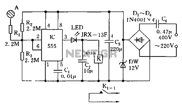
The touch sensor switch circuit diagram features a step-down rectifier circuit, a 555 timer, and flip-flops. When a hand touches the metal sheet A, the sensor signal activates the internal comparator of the 555 timer, setting the output to...
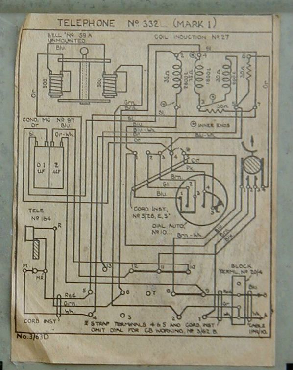
The induction coil is a component of the anti-sidetone circuit. It couples audio to the receiver and reduces the volume of the caller's own voice in the earpiece, which would otherwise be excessively loud compared to the incoming audio...
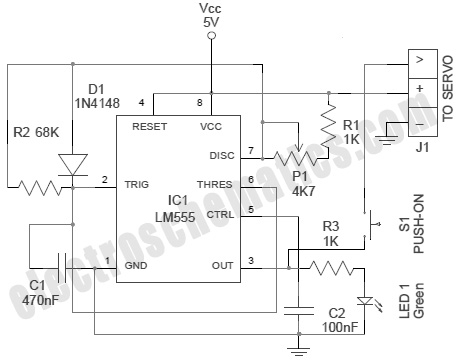
A servo is an error-sensing feedback control mechanism used to correct the performance of a system. A servo motor is a DC motor equipped with a servo mechanism. A servo motor is an electromechanical device that utilizes a closed-loop control...

This alarm features both open-loop and closed-loop detection systems along with an automatic alarm shutoff mechanism. It provides a 15-second delay for exit and entrance. Additionally, the alarm activation time can be adjusted from 1 to 15 minutes. The alarm...
This circuit provides a digital square wave that can be viewed directly or used to drive other circuits. It used the CMOS 4047 Low-Power Monostable/Astable Multivibrator. As used in Tom Duncan's Adventures with Digital Electronics Book, to drive CMOS...