
Digital Clock circuit with CMOS 4047
The described circuit utilizes the CMOS 4047, a versatile low-power monostable and astable multivibrator, to generate a digital square wave signal. This square wave can be employed for various applications, including driving other digital circuits or visual indicators like LEDs.
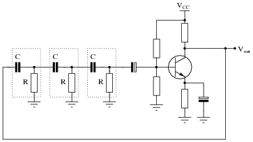
In the astable mode of operation, the 4047 generates a continuous square wave output. The frequency of this output is determined by the resistor-capacitor (RC) time constant, where the resistor (R) is set to 10 MΩ and the capacitor (C) is set to 100 nF. The calculated frequency of the square wave output is approximately 1 Hz, as derived from the formula \( f = \frac{1}{2 \cdot R \cdot C} \). This frequency corresponds to a duty cycle of 50%, resulting in a 1:1 mark-to-space ratio in the output waveform.
The 4047 provides multiple outputs: the primary output (Q), its inverse (notated as Q'), and an oscillator output (OscOut), which operates at double the frequency of the Q output. The Q output represents the square wave signal, while Q' provides the inverted square wave. The OscOut serves as a higher frequency alternative, suitable for applications requiring a faster signal.
To visualize the outputs, an LED can be connected in series with a 330 Ω resistor. This arrangement allows for direct observation of the square wave signal, with the LED turning on and off in accordance with the output frequency. The resistor is essential to limit the current flowing through the LED, protecting it from excess current that could lead to damage.
Overall, the CMOS 4047 multivibrator circuit is a practical solution for generating square wave signals, applicable in various electronic projects and systems requiring timing or waveform generation.This circuit provides a digital square wave that can be viewed directly or used to drive other circuits. It used the CMOS 4047 Low-Power Monostable/Astable Multivibrator. As used in Tom Duncan's Adventures with Digital Electronic's Book, to drive CMOS Decade of 4-bit binary counters.
RC = 10M x 100nF = (10x106) x (100x10-9) = 1 Hz OscOut (Double Frequency of Q) _ Q (Inverse of Q) Q (Square Wave, Frequency RC Hz, 1:1 Mark:Space Ratio) These 3 outputs can be viewed using an LED and 330R Resitor in series. 4047 Low-power astable/monostable multivibrator with oscillator output. 🔗 External reference
Related Circuits
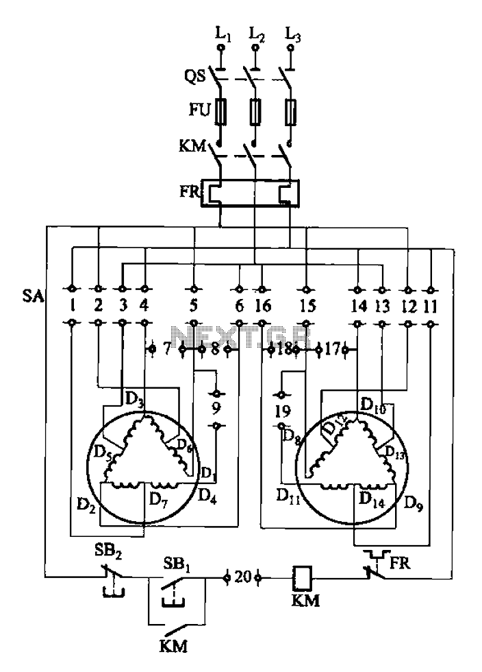
The 3-119 circuit shown in the figure combines switch SA to realize the stator windings, specifically the 2, Y, and 2Y connections, which correspond to the motor speed n1. The 3-119 circuit is designed to facilitate the control of motor...
The paraphase configuration is noteworthy for its ability to adjust either treble or bass, but not both simultaneously. The adjustments made to the tone controls directly influence the slope of the frequency response and the extent of bass and...
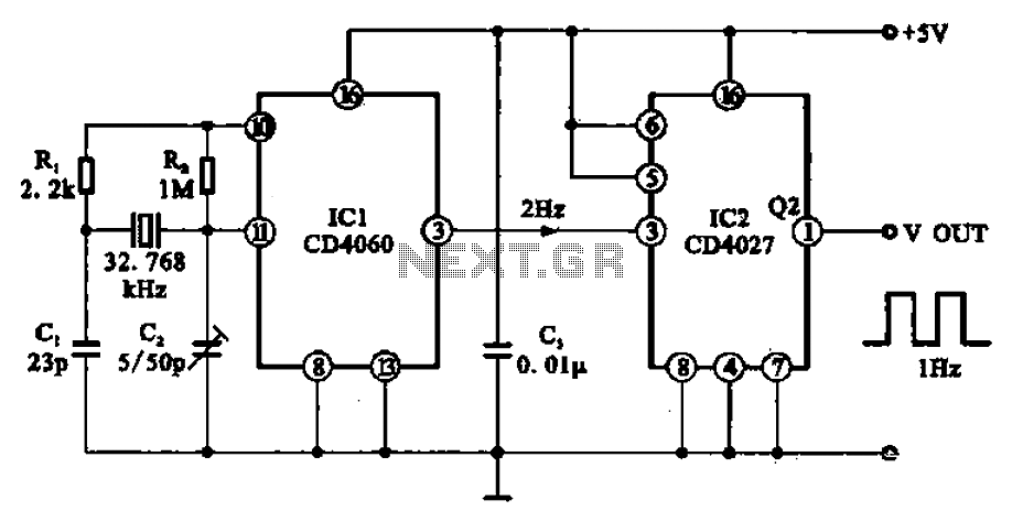
A 1Hz clock signal generator circuit is presented, which demonstrates a sophisticated clock signal generating mechanism. This circuit can be utilized for digital clocks and timing applications. It comprises a binary counter (CD4060), a JK flip-flop (CD4027), and a...
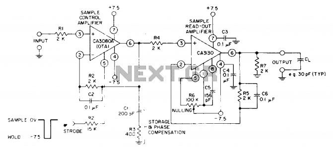
The circuit utilizes a CA3130 BiMOS operational amplifier as the sample-readout amplifier for the storage capacitor C1, while a CA3080A serves as the sample-control amplifier. Applications in linear systems that temporarily store analog data encompass digital voltmeter (DVM) systems,...
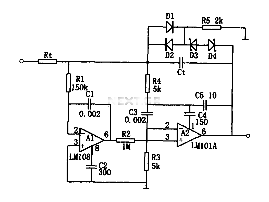
The high-speed integrating circuit is designed with an integration time constant circuit, RtCt, which offers a wide range. When the integrating capacitor Ct is not considered, A2 functions as a positive feedback compensation broadband AC amplifier. The negative feedback...
For successful circuit-building exercises, follow these steps: Measure and record all component values before constructing the circuit, selecting resistor values that are sufficiently high to minimize the risk of damaging any active components. In case of significant errors (greater...
Warning: include(partials/cookie-banner.php): Failed to open stream: Permission denied in /var/www/html/nextgr/view-circuit.php on line 713
Warning: include(): Failed opening 'partials/cookie-banner.php' for inclusion (include_path='.:/usr/share/php') in /var/www/html/nextgr/view-circuit.php on line 713