
H Bridge circuit

An H-bridge is a crucial circuit configuration in motor control applications, particularly for DC motors. It consists of four switches arranged in a bridge configuration, allowing current to flow through the motor in either direction, thus enabling forward and reverse motion. The four switches (SW1, SW2, SW3, and SW4) are typically implemented using MOSFETs or BJTs, which can be controlled by a microcontroller or other logic circuitry.
When SW1 and SW4 are closed while SW2 and SW3 are open, current flows through the motor in one direction, causing it to spin in a designated direction. Conversely, closing SW2 and SW3 while keeping SW1 and SW4 open reverses the current flow, causing the motor to spin in the opposite direction. This bidirectional control is essential for applications requiring precise movement, such as robotics or automated systems.
The inclusion of diodes (D1, D3, D4, and D5) serves an important role in protecting the circuit from back EMF generated by the motor during operation, particularly when the motor is switched off or rapidly changes direction. These diodes provide a path for the inductive kickback, preventing damage to the switches and other components.
The power supply connections in the H-bridge can be configured to provide the necessary voltage and current to the motor. If the load demands higher current or voltage than what is available from the control circuit, the supply lines can be decoupled to allow for independent power sources, ensuring that the motor operates efficiently without affecting control logic.
Simulation tools such as Proteus are invaluable for designing and testing H-bridge circuits. They allow engineers to visualize the operation of the circuit, simulate various scenarios, and debug potential issues before physical implementation. This ensures that the design is robust and functional, minimizing the risk of failure in real-world applications. Overall, the H-bridge circuit is a versatile and essential component in modern electronic motor control systems.H-bridge is a circuit configuration that allows the designer to apply the voltages in both directions. H-bridge also allows higher voltage and current to be applied to the load while controlling the direction through a low voltage signal.
The illustration below shows the flow of the H-bridge. Above Figure 1 is the diagram for the H-bridge. Switche s that are used to control the logic level are SW1, SW2, SW3, and SW4. D1, D3, D4, and D5 diodes are used to protect the reverse flow. The circuit in Figure 1 shows that the supplies to the load a well as the control are tied together. However, this can be separated if the load requires additional current and voltage. Both Figure 1 and Figure 2 shows the supply voltage in 2 different direction. The discussion above shows the implementation of the H-bridge to control direction. This can be used to control motor in both direction by controlling the switches. The proteus simulation above is used to test, debug as well as simulate the concept of the circuit to make sure that the circuit is workable. 🔗 External reference
Related Circuits
The TDA2030 is a monolithic integrated circuit in a Pentawat® package designed to function as a Class AB audio amplifier. It typically delivers up to 14 watts of output power (with a distortion rate of 0.5%) at 14V with...
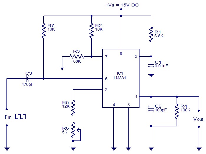
The following circuit illustrates a Frequency Voltage Converter Circuit. This circuit is based on the LM331 IC and operates with a supply voltage of 15V DC. The Frequency Voltage Converter Circuit utilizes the LM331 integrated circuit, which is designed for...
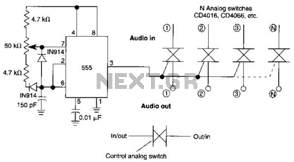
A 555 timer can be configured to simulate a multi-gang potentiometer by controlling the mark-space ratio. The switching rate should be at least twice the maximum expected signal frequency that the potentiometer has to handle. The 555 timer is an...
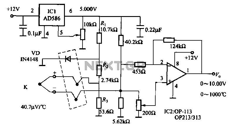
The circuit includes a K-type thermocouple cold junction compensation circuit, a precision 5.000V reference voltage source, and an OP113 operational amplifier. It is capable of measuring temperatures ranging from 0°C to 100°C with a resolution of 0.02°C. The OP113...
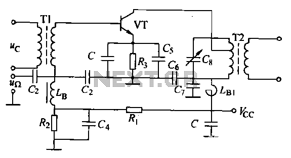
The circuit is designed for small-signal amplitude modulation (AM). Component C functions as a high-frequency bypass capacitor. Transformers T1 and T2 serve as high-frequency transformers, while the LC resonant circuit operates at the carrier frequency with a passband of...
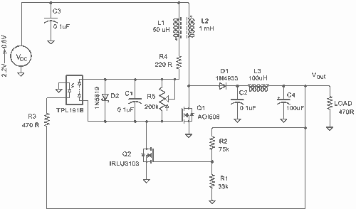
It employs a low threshold MOSFET and two coupled coils to function as a joule thief. An additional MOSFET is utilized for regulation. The circuit operates as a joule thief, which is a type of DC-DC converter designed to extract...