
One of the three-phase AC power circuit neutral wire break alarm
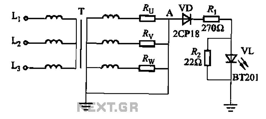
The neutral circuit alarm system plays a critical role in protecting electrical devices from potential damage due to unbalanced loads in a three-phase power system. The circuit operates by continuously monitoring the neutral point of the transformer. When the neutral line is functioning correctly, the VL LED indicator remains lit, signaling that the system is operating within safe voltage parameters.
In the event of an unbalanced load, the neutral point may experience a potential shift, leading to an increase in voltage that could harm connected appliances. The alarm circuit is designed to detect this shift and trigger an alert, thus preventing equipment damage. The variable power voltage regulator (T) allows for adjustments in voltage levels, enabling the circuit to adapt to varying load conditions.
The load resistors (Ru, Rv, Rw) are essential components that represent the various loads connected to the power system. Each resistor can simulate different operational scenarios, helping to evaluate the effectiveness of the alarm system under various conditions. The design of this circuit emphasizes reliability and responsiveness, ensuring that any deviation from normal operating conditions is promptly addressed.
Overall, the neutral circuit alarm system serves as a vital safeguard in three-phase electrical systems, providing essential monitoring and alerting functionalities to protect both the infrastructure and connected devices from the adverse effects of unbalanced loads. As we all know, if the power transformer neutral line circuit, and when the three-phase unbalanced load and can easily lead to electrical equipment (such as household appliance s, lamps, etc.) due to overvoltage (neutral point potential shift caused) damage. Neutral circuit alarm circuit is the use of transformer neutral line when following the path, the neutral point potential shift principles and design. Circuit shown in Fig. 13 + 80. When the power neutral line circuit, VL LED light. FIG, T is variable power voltage regulator, Ru, Rv, Rw of the load.
Related Circuits
Beeper and/or LED remotely-operated via mains supply line. Pressing the pushbutton of the transmitter, a sound and/or light alert is activated in the receiver. The system uses no wiring or radio frequencies: the transmitted signal is conveyed into the...
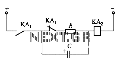
To fulfill the requirements of a control loop, it is often necessary to utilize an electromagnetic relay or a transistor relay to either accelerate or delay an action, thereby forming an acceleration or delay circuit. The circuit depicted in...
Converting periodic waveforms to square waves is essential for extracting clock signals from data, creating waveform generators, and developing timing-pulse generators. A square-wave conversion circuit is more advantageous when the duty cycle of the square wave is variable and...
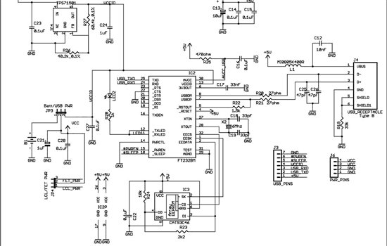
As found in SLAA458, the revised pulse oximeter application, an image of the USB schematic is attached, which is used to output collected data. There are a few questions regarding this schematic: 1) What do J3 and J6 correspond...
This triac-based 220V AC motor speed controller circuit is designed for controlling the speed of small household motors, such as drill machines. The motor speed can be adjusted by altering the setting of P1, which determines the phase of...
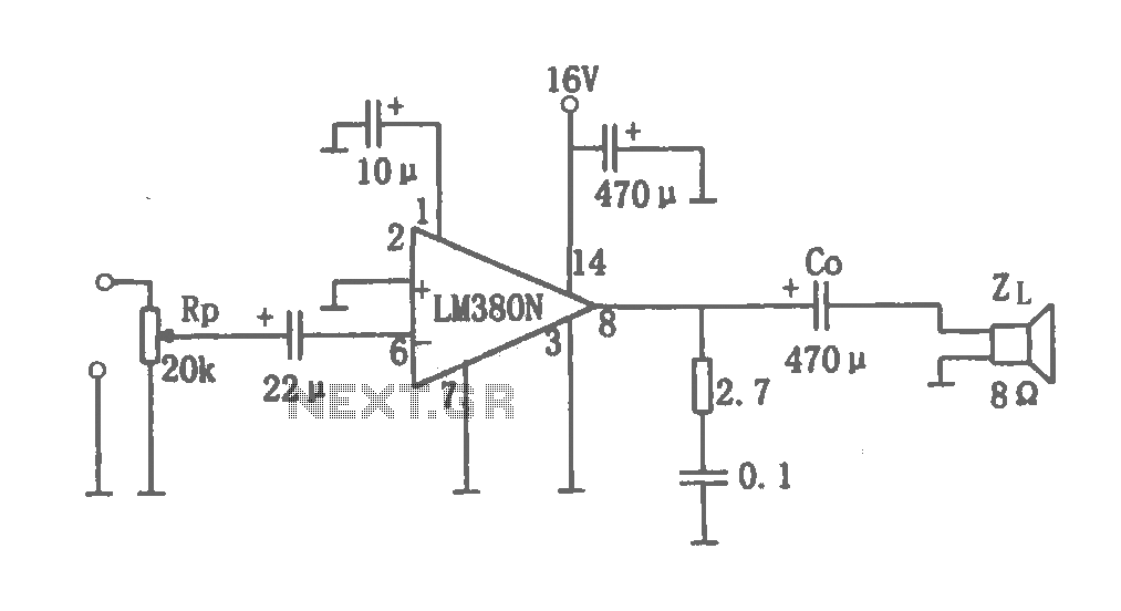
This document details a 2W audio power amplifier circuit that utilizes a 14-pin LM380 package as the amplification element. The input signal is managed by a volume control potentiometer (Rp) rated at 20k ohms, with a coupling capacitance of...
Warning: include(partials/cookie-banner.php): Failed to open stream: Permission denied in /var/www/html/nextgr/view-circuit.php on line 713
Warning: include(): Failed opening 'partials/cookie-banner.php' for inclusion (include_path='.:/usr/share/php') in /var/www/html/nextgr/view-circuit.php on line 713