
Delaying the release of DC relay circuit
The described circuit utilizes a combination of resistors, capacitors, and relay components to create a delay mechanism essential for control applications. In this configuration, the relay acts as a switch that can control the flow of current based on the voltage across the capacitor. The capacitor is charged through a resistor, and once it reaches a certain threshold voltage, it energizes the relay coil, causing the relay to actuate. The time it takes for the capacitor to charge to this threshold is determined by the values of the resistor and capacitor in the circuit.
The equations governing this circuit are fundamental to understanding the timing characteristics. The time constant, which affects how quickly the capacitor charges or discharges, is defined by the product of the resistance (R) and capacitance (C). The equation provided indicates that the maximum time delay can be adjusted by varying the resistance and capacitance values. This allows for precise control over the timing aspects of the relay operation, making it suitable for applications requiring specific timing sequences.
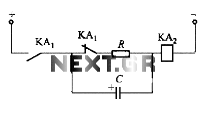
Figures 6-23 (a) to (c) represent configurations where the relay is pulled in instantly, but the release is delayed. This feature is particularly useful in applications where a load needs to remain powered for a certain period after the control signal has been removed. Conversely, Figure 6-23 (d) illustrates a scenario where both the pull-in and release actions are delayed, offering even greater control over the timing of the relay's operation.
In practical applications, the selection of the resistor and capacitor values must be done carefully to ensure that the desired timing characteristics are achieved. The reliability of the relay and the stability of the capacitor during operation are also critical factors that influence the overall performance of the circuit. This type of circuit is commonly used in various automation and control systems, where timing and sequencing of operations are crucial for efficient and safe operation.In order to meet the needs of the control loop, often require electromagnetic relay or transistor relay to accelerate or delay action, from action to constitute accelerate or delay circuit. Circuit shown in Figure 6-23. These types of circuit is the use of a capacitor charging and discharging of the relay coil to delay the release time Ran. Figure 6-23 (a) ~ (c) is the instantaneous pull, delayed release circuit; Figure 6-23 (d) to pull delay, release delay circuit.
The maximum time delay relay may be estimated by the following equation: t = 0 85R.. CX10-6 (s) where R: - the total circuit resistance, R: = R + RL, 0; R resistance, 0; foot L- relay coil resistance, N; C capacitance, pF.
Related Circuits
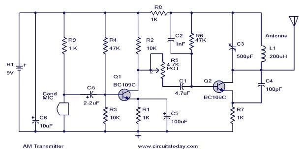
This document presents a circuit diagram of a simple AM transmitter that is capable of transmitting audio signals to a specified area. The circuit is designed with a limited power output to comply with FCC regulations while effectively producing...
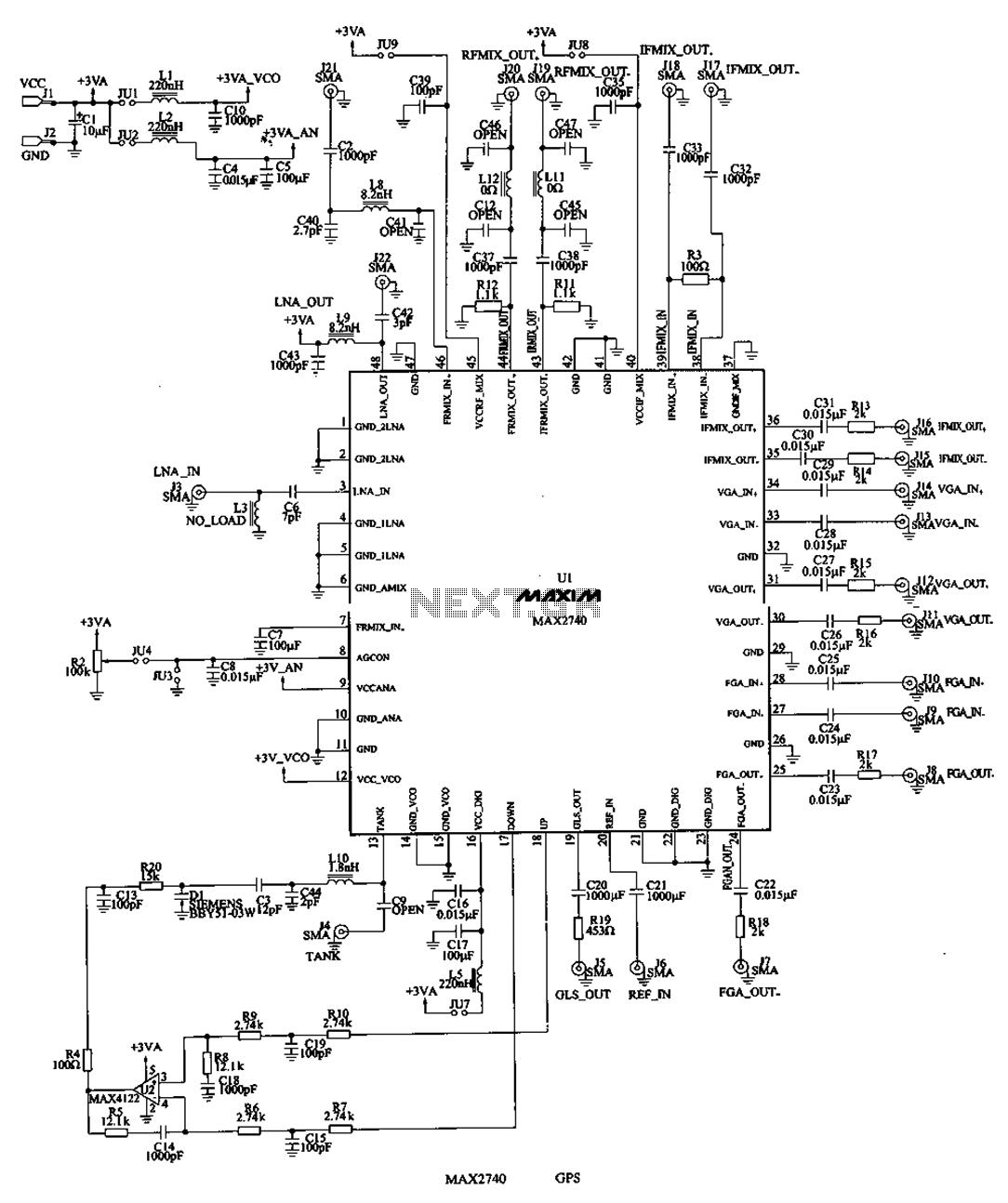
The MAX2740 is a complete GPS receiver down converter chip that processes the signal from the antenna to the input of digital signal processing. The receiver channel of the MAX2740 includes a low-noise amplifier (LNA), a downconverter, a variable...
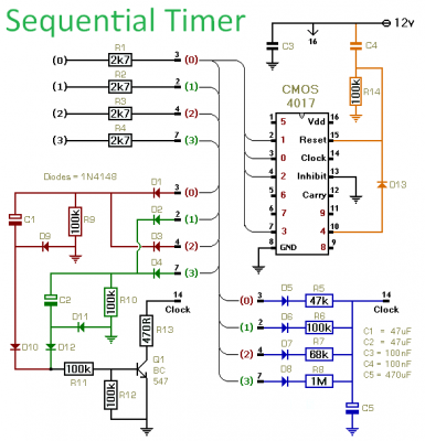
This timer is designed to generate a sequence of up to ten distinct events. Each event's duration can be set independently, and the sequence can be configured to run a predetermined number of times or continuously. Additionally, the individual...
This circuit is an adjustable voltage reference circuit, which serves as a voltage source that provides a voltage greater than that of the reference diode. High precision applications that operate over an extended temperature range necessitate a restriction on...
This project involves a 555 buzzer circuit utilizing the NE555 timer IC, which comes in an 8-pin DIP package and performs a wide variety of functions in electronic circuits. The circuit described will produce a buzzer sound when a...
This complete high quality, low noise 5-BAND GRAPHIC EQUALIZER circuit is based around Monolithic Linear integrated circuit LA3600 manufactured by SANYO. This circuit is very easy to build and has good Quality. You can use it with Portable component...
Warning: include(partials/cookie-banner.php): Failed to open stream: Permission denied in /var/www/html/nextgr/view-circuit.php on line 713
Warning: include(): Failed opening 'partials/cookie-banner.php' for inclusion (include_path='.:/usr/share/php') in /var/www/html/nextgr/view-circuit.php on line 713