
BF494 Transistor For UHF Indicator Wavemeter

The UHF Indicator Wavemeter Circuit is designed to measure and indicate the frequency of ultra-high frequency (UHF) signals. The circuit primarily employs two BF494 transistors, which are known for their high-frequency performance and low noise characteristics, making them suitable for oscillator applications.
The core of the circuit consists of an oscillator that generates a frequency signal. The BF494 transistors are configured in a common emitter arrangement, which enhances the gain and allows for efficient oscillation. The oscillator's output is typically coupled to a frequency counter or a display circuit to provide a visual indication of the measured frequency.
The circuit may also include additional components such as resistors, capacitors, and inductors, which are essential for tuning the oscillator to the desired frequency range. The values of these passive components can be adjusted to optimize the performance of the circuit, ensuring accurate frequency measurement across the UHF spectrum.
In practical applications, the UHF Indicator Wavemeter can be used for testing and aligning UHF transmitters and receivers, as well as for educational purposes in electronics laboratories. Proper shielding and layout considerations should be taken into account to minimize interference and ensure reliable operation of the circuit. Overall, this circuit serves as a valuable tool for engineers and hobbyists working with UHF signals.The following circuit shows about UHF Indicator Wavemeter Circuit Diagram. This circuit using dual BF494 Transistor. Features: oscillator is .. 🔗 External reference
Related Circuits

This schematic outlines a simple electronic circuit designed to indicate water levels using a 7-segment display. The circuit shows water levels by displaying 'L', 'H', and 'F' for low, half, and full levels, respectively. It is based on the...
This astable multivibrator utilizes incandescent lamps instead of collector load resistors. The lamps flash on and off alternately. The circuit operates as an astable multivibrator, which is a type of oscillator that continuously switches between its high and low states...
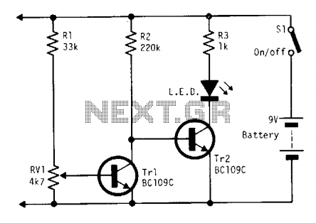
Continuously monitors battery voltage during use and consumes only about 250 microamperes until the end point is reached. Near the end point, transistor Tr1 turns off, allowing transistor Tr2 to illuminate the LED, which increases current drain further, leading...
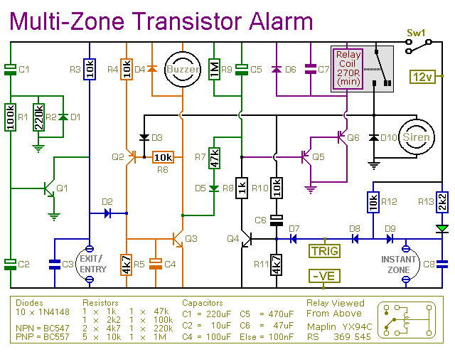
This is a simple transistor-based burglar alarm circuit. Its features include automatic exit and entry delays, along with a timed bell cut-off and reset. It is designed to be used with standard types of normally-closed input devices such as...
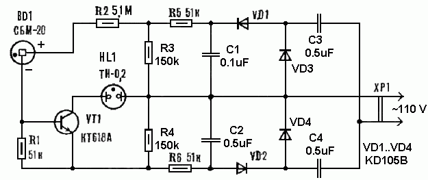
Measuring radiation does not require expensive factory-made instruments. A simple device can be constructed using a radiation detector, such as the SBM-20 or a similar type. The circuit operates on 220 volts AC at 50/60Hz. The double-voltage rectifier circuit...
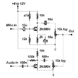
This two-channel audio mixer utilizes 2N3904 transistors to create two preamplifiers. The first preamplifier is designed for high gain, suitable for microphone input, while the second preamplifier allows for control over the audio level input. The audio mixer requires...