
DK-5A, DK-5AD AC power control circuit

The DK-5A and DK-5AD AC power control circuit is a fundamental component in managing the operation of various electrical devices. The circuit typically consists of a power source, a control switch, and an electromagnet coil, which collectively facilitate the control of AC power delivery.
In the schematic, the closing button (SBz) serves as a manual input for activating the circuit. When the button is pressed, it completes the circuit, allowing current to flow through to the electromagnet coil (U). This coil, when energized, generates a magnetic field that can be used to actuate mechanical switches or relays, enabling or disabling the power supply to connected loads.
The line (YA) indicates the connection from the closing button to the electromagnet coil, ensuring that the coil receives the necessary voltage to operate. The design of this circuit allows for safe and efficient control of AC power, making it suitable for various applications in industrial and commercial settings.
The circuit may also include protective components such as fuses or circuit breakers to prevent overloads and ensure the safety of the system. Additionally, the integration of indicator lights can provide visual feedback on the status of the circuit, enhancing usability and safety for operators.
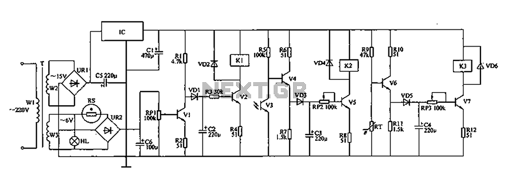
Overall, the DK-5A and DK-5AD AC power control circuit exemplifies a straightforward yet effective design for managing AC power, demonstrating the essential principles of electrical control systems.DK-5A, DK- 5AD AC power control circuit circuit shown in Figure 6-77. Figure, SBz the closing button, YA line for the closing electromagnet coil, U., For the operation of the power control box.
Related Circuits
This key code switch circuit is an electronic circuit designed to replace conventional key switches, eliminating the need for physical key inserts. The key code switch circuit utilizes a microcontroller or a dedicated integrated circuit (IC) to interpret key codes entered...
The SE555/NE555 timer was first introduced by the Signetics Corporation around 1971. Pin connections and functions are as follows: Pin 1 (Ground) - This pin serves as the ground or common pin, representing the most negative supply potential of...
The automatic controller for a chicken coop is designed to automatically regulate light, temperature, and humidity, thereby enhancing egg production and survival rates of chickens. This device is intended for specialized poultry households in rural areas. The circuit operates...
The circuit operates on the principle of a transformer, bridge rectifier, and conditioning for battery charging. The charging current can be adjusted to approximately 12V at 100A. For battery charging, a charging rate of 10 hours requires a charging...

This smoke detector electronic project is designed using the LM1801 and common electronic components. The smoke detector circuit diagram does not utilize ionization detection, gas sensors, or optocouplers; instead, it employs two photoresistors (LDRs) and an LED. The circuit...
Quasi square wave resonant converters, also referred to as quasi resonant (QR) converters, facilitate the design of flyback Switch Mode Power Supplies (SMPS) with diminished Electro Magnetic Interference (EMI) and enhanced efficiency. Due to their low noise generation, QR...