
RS-232 Serial Interface Status Indicator Circuit

The RS-232 Serial Interface Status Indicator Circuit is designed to provide visual feedback regarding the status of data transmission and reception in RS-232 communication. The circuit primarily employs a logic integrated circuit (IC), which simplifies the design while ensuring reliable operation.
The circuit typically includes two LED indicators: one for TXD (transmit data) and another for RXD (receive data). These LEDs illuminate when the respective data lines are active, providing a clear visual indication of communication activity.
The operation of the circuit is based on monitoring the voltage levels on the TXD and RXD lines. When data is being transmitted, the TXD line will exhibit a change in voltage, which is detected by the logic IC. The IC then drives the TXD LED, turning it on to indicate that data is being sent. Similarly, the RXD line is monitored for incoming data, and when activity is detected, the RXD LED is illuminated.
Power supply considerations are crucial for the circuit's performance. The circuit can be powered by a standard voltage supply, typically 5V or 12V, depending on the specifications of the logic IC used. Proper decoupling capacitors should be employed near the power pins of the IC to minimize noise and ensure stable operation.
In summary, the RS-232 Serial Interface Status Indicator Circuit is a practical solution for visualizing data transmission and reception in serial communications, leveraging a simple logic IC to drive LED indicators for effective status monitoring. This design is particularly beneficial in debugging and monitoring serial communication systems.RS-232 Serial Interface Status Indicator Circuit. I designed this circuit many years ago and have used it several times since. It uses a single logic IC to indicate the TXD and RXD. 🔗 External reference
Related Circuits
Four simple 12V power supply circuits are designed to provide output voltages close to 12V. The first power supply circuit utilizes a BD139 transistor, a zener diode, and several passive components. Each schematic is straightforward to assemble and will...
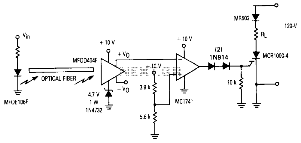
An operational amplifier (op amp) is utilized to connect a fiber optic system with a MOS SCR for multi-cycle, half-wave control of a load. This receiver features two complementary outputs: one maintains a quiescent level of approximately 0.6 V,...
This interface is needed to connect the phone to a PC, because the PC's serial port works with voltage levels between -12 and 12V (RS232 protocol) and the phone operates between 0 and 5V (TTL protocol). Don't even think...

The 78W series voltage regulators are designed to handle an input voltage of approximately 35V, while the 24V type can withstand up to 40V. It should be noted that these regulators will not operate effectively with a significant input-output...
With this circuit can determine whether any of the phones of the same line is busy (it's up the handset), with the help of a LED. The circuit has no measurable effect on the telephone, so that there are...
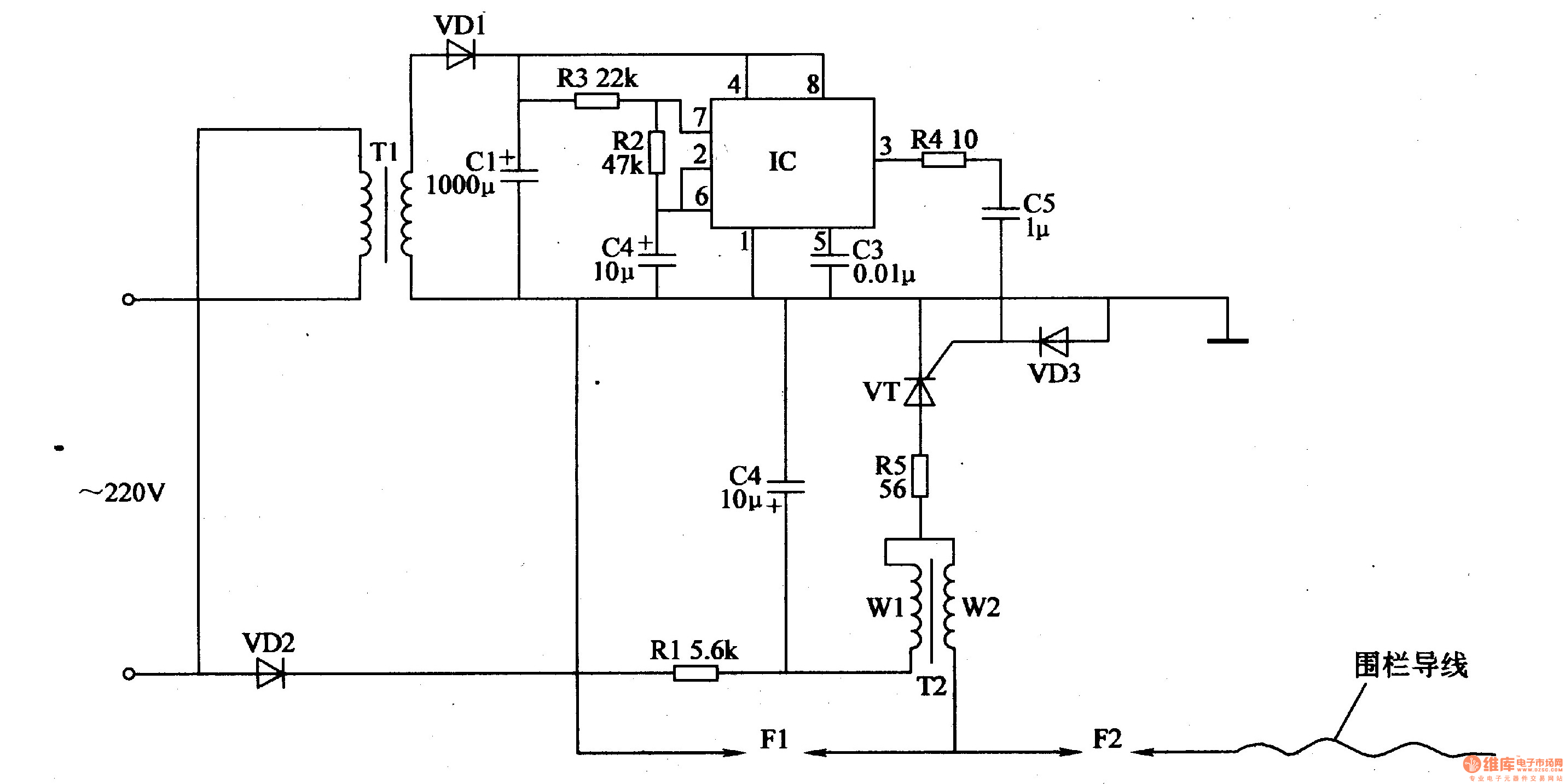
The electric fence control circuit consists of a power supply circuit, a pulse generator, and a high-voltage circuit, as illustrated in Figure 4-27. The power supply circuit includes a power transformer (T1), rectifier diodes (VD1, VD2), filter capacitors (C1,...