
Timer With On-Off Delay
The 555 timer is a versatile device widely used in various timing applications. In this specific configuration, the circuit operates in monostable mode, where the timer generates a single output pulse in response to an external trigger. The duration of the pulse, which corresponds to the "on" time, can be adjusted by varying the resistance and capacitance in the timing network.
The circuit typically consists of a 555 timer IC, a resistor (R), a capacitor (C), and a switch to initiate the timing sequence. When the switch is closed, the capacitor begins to charge through the resistor, and the output of the 555 timer transitions from low to high. The time period for which the output remains high is determined by the formula T = 1.1 * R * C, where T is the time in seconds, R is the resistance in ohms, and C is the capacitance in farads.
To create an off delay, the circuit can be designed such that once the output goes high, it remains high for the predetermined time before returning to low. This can be particularly useful in applications where a device needs to be activated for a specific duration before shutting off automatically.
In addition to the basic components, it may also include diodes for protection against reverse polarity and to ensure proper discharge of the capacitor. The output can be used to drive other devices, such as LEDs, relays, or other electronic components, making this circuit highly adaptable for various applications in automation and control systems.// 555 Timer With On Off Delay Circuit Here is a timer circuit using common IC 555. The circuit is designed to facilitate time adjustment of both. 🔗 External reference
Related Circuits
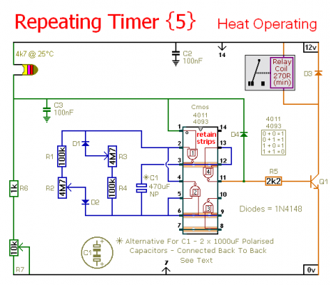
This circuit is a temperature-controlled version of Repeating Timer No. 3. The light-dependent resistor has been replaced by a temperature-dependent resistor, or thermistor. A small preset potentiometer allows the user to select the temperature threshold above which the timer...
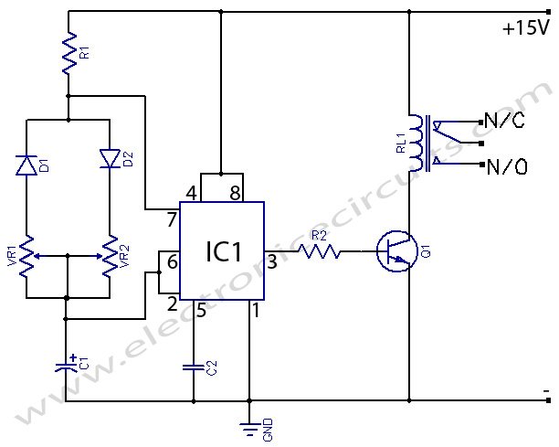
Today, solutions are offered for a timed control relay that utilizes Normally Open (NO) and Normally Closed (NC) contacts to manage the operation of other devices, enabling or disabling them as needed. The functionality of this circuit is based...

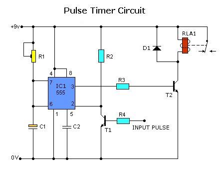
The timing interval is initiated by applying power and is determined by the resistor-capacitor (RT-CT) combination. At the end of the interval, a unijunction transistor triggers a silicon controlled rectifier (SCR) to apply nearly the full supply voltage to...
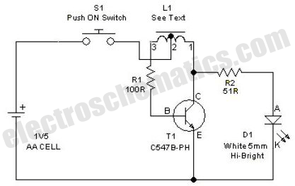
This simple LED driver circuit allows the operation of up to seven LEDs using a single NiMH (Nickel Metal Hydride) AA cell. The circuit generates voltage pulses. The LED driver circuit is designed to efficiently power multiple LEDs while maintaining...
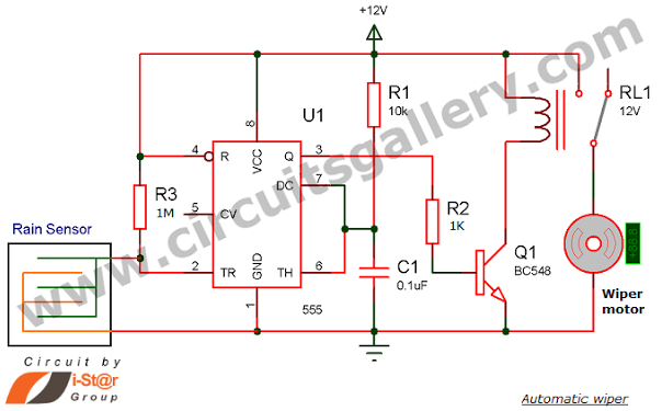
Have you seen Audi, Lexus, or Ford rain-sensing wipers and wondered how they operate in these vehicles? They are controlled by sensors located at the center of the windscreen, which detect raindrops and activate the wiper motor. The functioning...
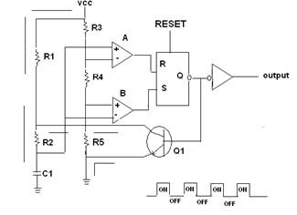
A 555 timer IC is utilized as an astable multivibrator, as illustrated in the accompanying figure (A). The threshold input is connected to the trigger input (Pin 2). The resistor R1, resistor R2, and capacitor C1 form the timing...