
op amp A probably very easy Op-Amp Analysis

The circuit in question involves a grounded node and resistors arranged in a specific configuration. The initial conditions indicate that V+ is set to 0 volts due to grounding, which significantly influences the circuit's behavior. The 3-ohm resistor carries a current of 5A, resulting in a voltage drop across it calculated by Ohm's Law (V = IR), yielding a voltage V_A of 15 volts.
The next step involves analyzing the behavior of the voltage at node V_-, which is influenced by the surrounding resistors. The equation derived, (V_-) - 15)/2 ohm + (V_0 - V-)/3 ohm = 0, suggests the presence of a more complex network of resistors that must be considered to solve for the unknown voltages. This equation can be rearranged to express V_- in terms of V_0 and the known voltage drop across the 2-ohm resistor.
It is critical to recognize that while the exercise may utilize idealized values for ease of calculations, practical applications of operational amplifiers typically involve limitations regarding current sourcing and sinking capabilities. Real-world op-amps generally operate within certain parameters, which should be emphasized in educational settings to prepare students for practical circuit design and analysis.
In conclusion, to solve the circuit, one must carefully analyze the relationships between the voltages at various nodes, taking into account the constraints posed by the resistors and the operational amplifier's characteristics. The final solution will provide insights into the circuit's performance and validate the initial assumptions made regarding V_A and V+.I`ve been getting that V_A = 15 (which is wrong). Also I think V+ is = 0 since the node below 3 ohm is grounded. Any help on how to start solving this Ok! So, what I did at first was: V+ = 0, the current 5Am is going through 3 ohm resistor => Va- 0 = 3 *5 = 15. Afterwards (V_-) - 15)/ 2ohm + (V_0 -V-)/3ohm = 0 I understand this is just for learning electronic circuit analysis and one of the goals is of course to be able to work with nice round numbers, but be aware that in practice the average opamp can sink/source nowhere near the 2A that it does here. I mean, what is wrong to get students used to work with practical values OK, I said my thing, now solve the circuit :o) jippie Apr 2 `13 at 18:22
🔗 External reference
Related Circuits
This circuit is a variable output switching regulator designed for general-purpose applications. An LM105 positive regulator serves as the amplifier-reference for the switching regulator. Positive feedback to induce switching is derived from the LM105 at pin 1 through an...
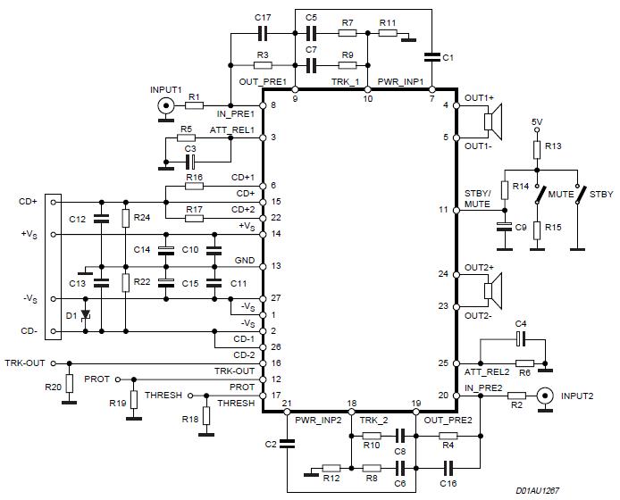
The Stereo Power Amplifier utilizes a 2x70Watt STA550 chip designed for audio power applications, featuring a BASH concept that allows connection to digital devices. This amplifier operates on a BTL (Bridge-Tied Load) system with a symmetrical power supply that...
This circuit is designed to drive a low-power speaker using a sound effects module or a noise generator. It can also be utilized to create amplified speakers for computer use. The circuit amplifies the input signal by a factor...
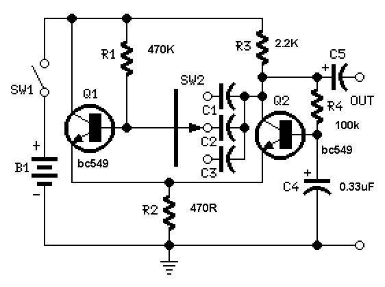
A useful feature of this circuit is that the frequency can be changed by modifying the capacitor value. A switch can be added to select between various frequencies. This circuit utilizes a capacitor in conjunction with an oscillator to determine...
This 18 dB gain amplifier was constructed using the Manhattan-style technique to assess the Linear Technology LT1253 dual video amplifier as a potential output amplifier for Direct Digital Synthesis (DDS) systems that utilize the Analog Devices AD9850 and similar...
Two reasons why the LM101 is well-suited for comparator applications are its large differential input voltage range and the ease of clamping the output. The LM101 operational amplifier is particularly advantageous for use in comparator circuits due to its significant...