
amp variable output switching regulator lm195

The variable output switching regulator circuit is designed to efficiently convert a varying input voltage into a stable output voltage suitable for various applications. The core component, the LM105, functions as a precision voltage reference and amplifier, allowing for accurate feedback control. The integration of an LM103 diode facilitates the positive feedback loop that is essential for initiating the switching action of the regulator.
The feedback mechanism operates by sensing the output voltage and adjusting the duty cycle of the switching action through the internal amplifier. The inductor L1, in conjunction with the output capacitor C2, forms a low-pass filter that smooths the output voltage, ensuring that it remains stable despite fluctuations in input voltage or load conditions. This design allows for a more efficient operation compared to linear regulators, as it minimizes power loss by switching the pass devices fully on or off rather than operating in a linear region.
The use of four LM195 power transistors in parallel is a strategic choice to achieve the desired output current of 6 amps. Each LM195 can handle a maximum of 2 amps, and by paralleling them, the circuit can distribute the load evenly without the need for additional ballasting resistors. This simplifies the design and enhances reliability, as unequal current sharing can lead to thermal runaway in power transistors. The configuration ensures that when Q1 is turned on, the bases of the LM195s are elevated to the supply voltage, effectively preventing any base current from flowing into the transistors, since the input PNP transistors are reverse-biased, thus maintaining efficient operation of the regulator.
Overall, this circuit exemplifies a robust solution for applications requiring a reliable and adjustable power supply, leveraging the strengths of the LM105 and LM195 components to deliver high performance in a compact design.This circuit is the variable output switching regulator for general purpose applications. An LM105 positive regulator is used as the amplifier-reference for the switching regulator. Positive feedback to induce switching is obtained from the LM105 at pin 1 through an LM103 diode. The positive feedback is applied to the internal amplifier at pin 5 a nd is independent of supply voltage. This forces the LM105 to drive the pass devices either on or off, rather than linearly controlling their conduction. Negative feedback, delayed by L1 and the output capacitor, C2, causes the regulator to switch with the duty cycle automatically adjusting to provide a constant output.
Four LM195`s are used in parallel to obtain a 6 amp output since each device can only supply about 2 amps. Note that no ballasting resistors are needed for current sharing. When Q1 turns on all bases are pulled up to V+ and no base current flows in the LM195 transistors since the input PNP`s are reverse biased.
🔗 External reference
Related Circuits
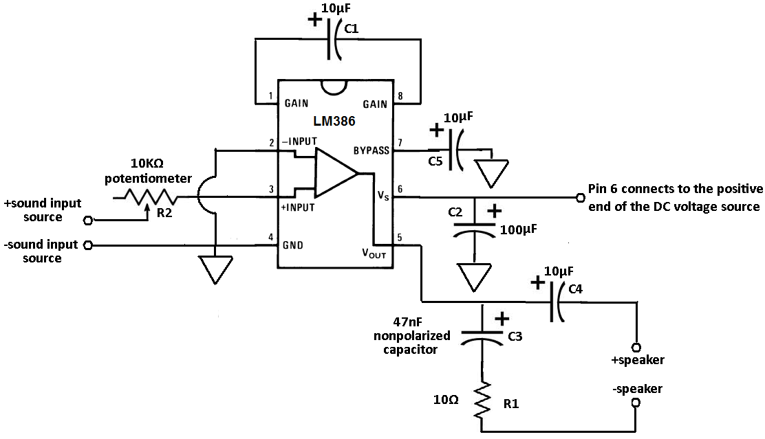
Terminals 1 and 8 serve as the gain control for the amplifier. Adjustments to the gain can be made by connecting a resistor and capacitor, or just a capacitor, between these terminals. In this circuit, a 10 µF capacitor...
To order boards, click to access the ESP Purchase form. Verify the price and postage, then open the order form, fill it in, and print it from your browser. Boards are sold only as a stereo pair and are...
Here is the schematic for an 8 watt audio amp. This amp can be used as a simple booster, the heart of a more complicated amplifier or used as a guitar amp. The circuit can be built on a...
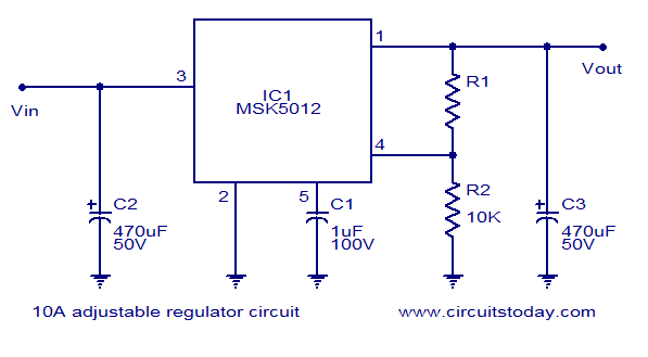
A reliable 10A adjustable voltage regulator based on the MSK5012, featuring an output voltage range of 1.3 to 30V. It is characterized by low ripple and high efficiency. The MSK5012 adjustable voltage regulator is designed for applications requiring a stable...

This circuit was designed to provide that continuous light lamps already wired into a circuit become flashing. Simply insert the circuit between existing lamp and negative supply. Especially suited for car or panel pilot lights, this device can drive...
This article presents a driver circuit for a 12V, 5W fluorescent lamp. The circuit utilizes a standard 220V to 10V step-down transformer operated in reverse to achieve a 12V output. The driver circuit for a 12V, 5W fluorescent lamp is...