
Simple Square wave Generator using transistors ~ Easy Electronics

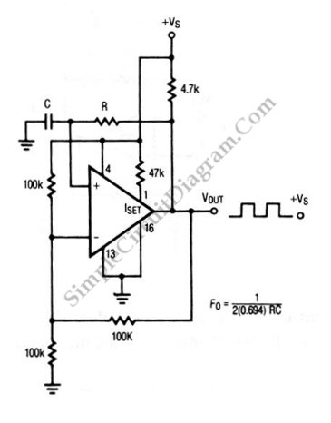
This circuit utilizes a capacitor in conjunction with an oscillator to determine its operating frequency. The fundamental principle behind this design is based on the relationship between capacitance and frequency in an RC (resistor-capacitor) network. By adjusting the value of the capacitor, the time constant of the circuit changes, which in turn alters the frequency of the output signal.
The circuit can be enhanced by incorporating a switch that allows the user to select from multiple capacitors, each corresponding to a different frequency. This can be achieved using a rotary switch or a toggle switch connected to a bank of capacitors. Each position on the switch connects a different capacitor in parallel or in series with the existing capacitor in the circuit, thus providing the capability to select various frequency outputs.
In terms of components, the circuit typically includes a resistor, a capacitor, and an oscillator circuit, which may be implemented using a 555 timer IC or a similar component. The resistor value can also be adjusted to further refine the frequency range.
The output signal can be monitored using an oscilloscope or a frequency counter to verify the frequency changes as the capacitor value is modified. This flexibility makes the circuit suitable for applications in signal generation, audio tone generation, and other scenarios where variable frequency output is required.
Overall, this circuit design promotes versatility and adaptability, allowing users to customize the frequency output according to specific requirements.An useful feature of this circuit is that the frequency can be changed by changing a capacitor value, a switch can be add to choose between various frequencies. 🔗 External reference
Related Circuits
This metal detector schematic circuit is based on a transistor radio as a detector. This metal detector is entirely different from other metal detectors because this circuit does not have a speaker. With the radio tuned to a weak...
The circuit depicted in this schematic diagram is a square-wave oscillator circuit. The primary component of this oscillator circuit is the LP165/365 comparator. The square-wave oscillator circuit utilizes the LP165/365 comparator to generate a continuous square wave output. The...
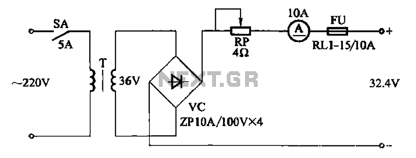
The adjustment potentiometer RP can modify the charging current. The adjustment potentiometer, designated as RP, serves a critical role in regulating the charging current within an electronic circuit. This component is typically a variable resistor that allows for fine-tuning of...

This is a simple smoke alarm circuit using a timer IC, the NE555. The circuit operates by illuminating a Light Dependent Resistor (LDR) with a lamp. When smoke obscures the light from the lamp, the resistance of the LDR...

Use #22 Hook-up Wire for Windings. Numbers on coil are connection points to the FAR Circuits PC board. More: Voltages shown are typical values using a 9V battery. C3,C5 are three gang variable capacitor 10-60pF/gang. Many substitutes are possible....
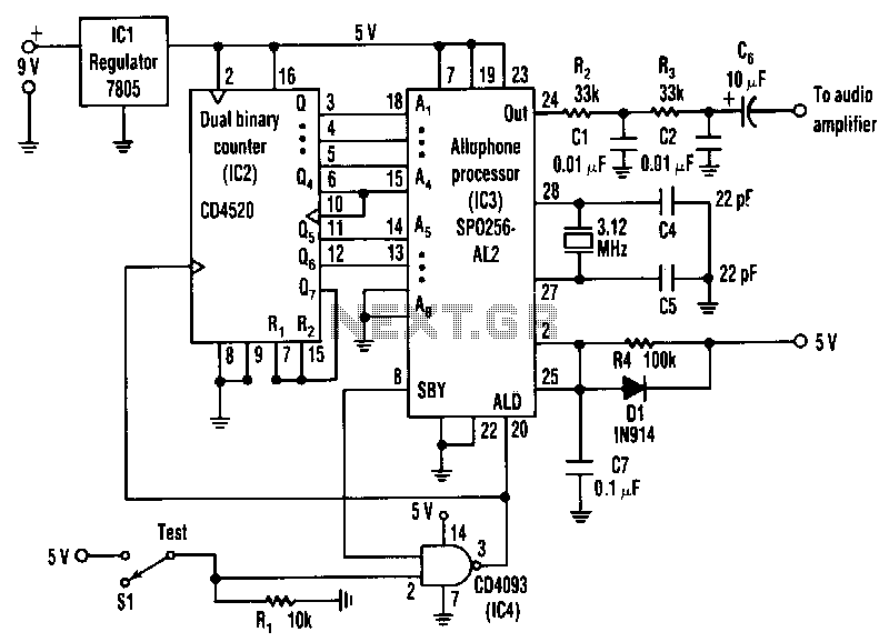
The circuit is a general-purpose system with various applications that vocalizes 59 allophones stored in the speech processor. After filtering and amplification, its pulse-code-modulated output can drive an 8-ohm speaker. The address pins of the processor, labeled A1 to...