
Op-Amp Application: Level Shifting Amplifier
In linear circuit design, the process of amplifying a voltage that is referenced to a specific DC level is crucial for various applications, such as signal conditioning, audio amplification, and sensor interfacing. This involves using operational amplifiers (op-amps) configured in a non-inverting or inverting amplifier configuration, depending on the desired gain and output characteristics.
The op-amp receives an input voltage (V_in) that is offset by a DC bias voltage (V_ref). The output voltage (V_out) is then expressed as a function of the input voltage and the gain determined by external resistors. In a non-inverting configuration, the gain (A) can be calculated using the formula A = 1 + (R_f/R_in), where R_f is the feedback resistor and R_in is the input resistor. The output voltage can be represented as V_out = V_ref + (V_in * A).
It is essential to ensure that the op-amp operates within its specified voltage range to avoid saturation and distortion of the amplified signal. Additionally, considerations such as bandwidth, slew rate, and power supply requirements must be taken into account when designing the circuit.
The output can then be used in various applications, including driving loads, interfacing with analog-to-digital converters, or further processing in subsequent stages of a more complex electronic system. Proper filtering and decoupling techniques should be implemented to minimize noise and ensure stable operation of the amplifier circuit.Sometimes, in linear equipment design, it`s necessary to take a voltage which is referred to some dc level and generate an amplified output which is referred.. 🔗 External reference
Related Circuits
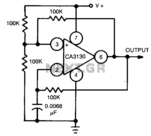
This circuit utilizes the CA3130 BiMOS operational amplifier, which operates at a frequency of 1 kHz. It features a rail-to-rail output swing, ensuring that the output can reach the supply voltage levels. The frequency of operation remains independent of...
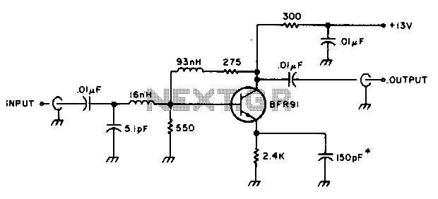
The amplifier delivers a gain of 10 dB across a frequency range of 10-600 MHz and features a 1-to-1 impedance match at 50 ohms. The BFR91 transistor exhibits a noise figure of 1 dB at 500 MHz. The circuit...
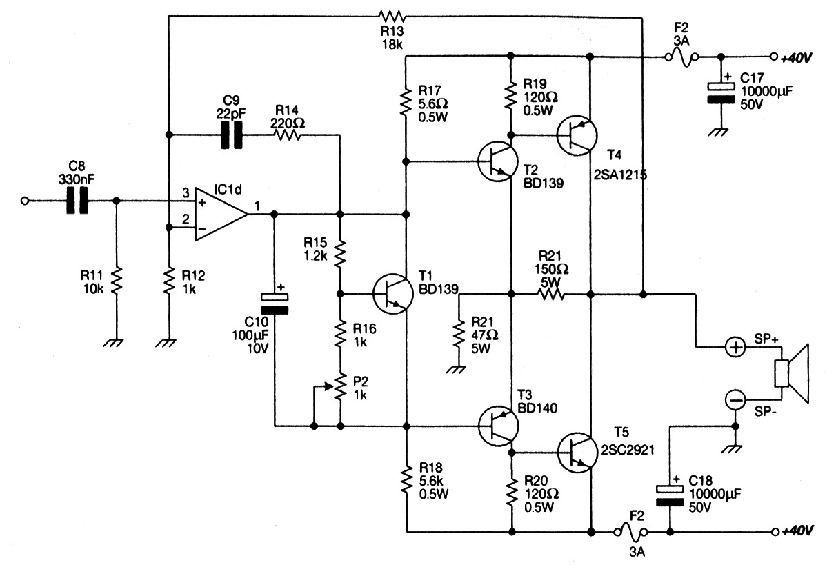
Main Power Amplifier OCL 100 watt using MJ802 and MJ4502 transistors. It is designed to provide strong bass and bold treble, making it suitable for various applications such as parties or home theater systems. This Class AB amplifier delivers...
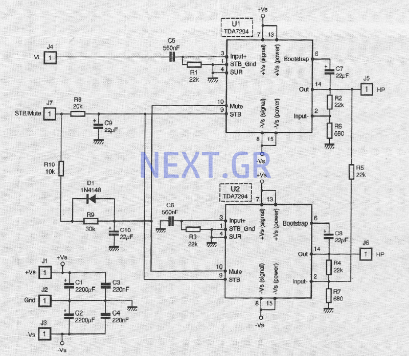
The TDA 7294 from T-MICROELECTRONICS is a monolithic integrated circuit housed in a "Multiwatt 15" package, primarily designed for use in Class AB amplifiers for high-fidelity applications, including stereo systems, active speakers, and television receivers. Its large feed area...
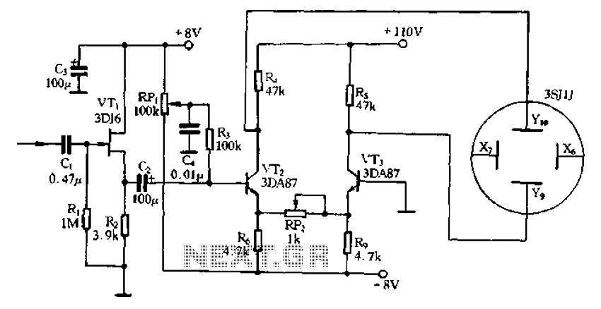
Application of the differential amplifier circuit in a simple small oscilloscope. The differential amplifier circuit is a crucial component in the design of a simple small oscilloscope. This circuit is designed to amplify the difference between two input voltage signals...

This unit is designed to connect to an existing car stereo amplifier, providing the additional "punch" often desired in music playback by driving a subwoofer. Since very low frequencies are omnidirectional, a single amplifier is needed to power this...