
Application of the differential amplifier circuit in a simple small oscilloscope
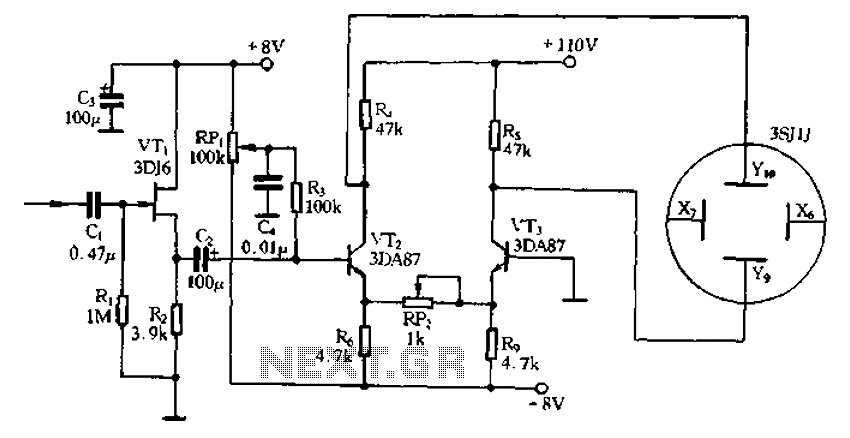
The differential amplifier circuit is a crucial component in the design of a simple small oscilloscope. This circuit is designed to amplify the difference between two input voltage signals while rejecting any common-mode signals, making it ideal for applications where precision and noise immunity are essential.
In the context of a small oscilloscope, the differential amplifier can be utilized to measure voltage signals from various sources, such as sensors or other electronic circuits. The circuit typically consists of operational amplifiers (op-amps) configured in a differential mode, which allows for high input impedance and low output impedance. This configuration ensures that the oscilloscope can accurately capture and display the voltage waveform without loading the source.
The differential amplifier circuit includes resistors that set the gain of the amplifier, allowing for adjustments based on the specific requirements of the measurement. The output of the differential amplifier feeds into the analog-to-digital converter (ADC) of the oscilloscope, converting the amplified analog signal into a digital format for processing and display.
Additionally, the small oscilloscope may incorporate features such as a display unit, control buttons for adjusting time base and voltage scale, and power supply circuitry to ensure stable operation. The overall design emphasizes portability and ease of use, making it suitable for both educational purposes and field applications. By effectively utilizing the differential amplifier, the small oscilloscope can provide accurate waveform representations, facilitating analysis and troubleshooting in various electronic systems.Application of the differential amplifier circuit in a simple small oscilloscope
Related Circuits
This is a power audio amplifier circuit based on the STK400xx series. It provides high-quality sound and is cost-effective, as the STK40xx series is affordably priced. The circuit can be easily constructed using only a few external components. The...
The 5W/6V solar panel can achieve a maximum current of approximately 500 to 800mA, peaking at 800mA during noon. Limiting the current to 150mA appears inefficient. A 1W panel can supply around 160mA during peak performance for up to...
Model Railroader is the world's largest magazine on model trains and model railroad layouts. It offers assistance for both beginners and advanced enthusiasts across all model railroading scales, including layout track plans, product reviews, news, and forums. Model Railroader magazine...
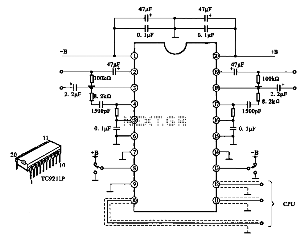
A typical electronic volume control circuit is commonly used in stereo audio devices connected through a computer (CPU). The circuit adjusts the volume of stereo signals via input and output pins. Control signals are sent to the CPU (including...
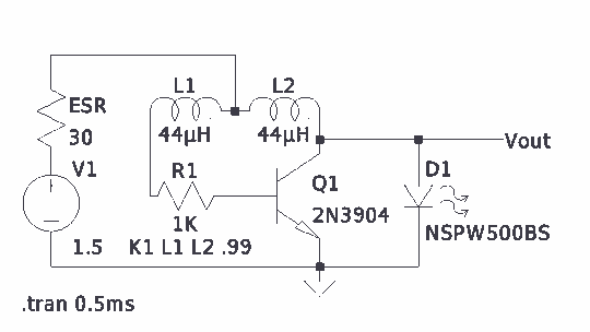
There is much pleasure in useless knowledge. The value of the inductors (44 µH) was determined using an online toroid calculator, specifying an FT-50-43 toroid with 10 turns through it. The described circuit involves the use of an FT-50-43 toroidal...
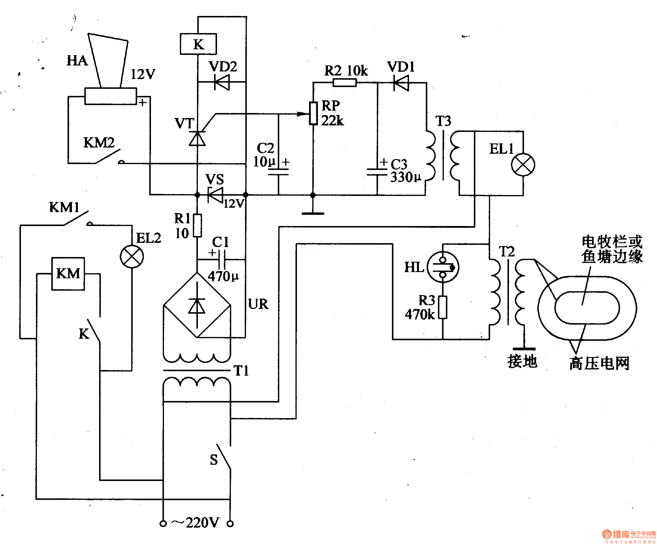
The electric fence control circuit consists of three main components: the power supply circuit, the high voltage circuit, and the sound and light alarm circuit, as illustrated in Figure 4-26. The power supply circuit includes a power switch (S),...
Warning: include(partials/cookie-banner.php): Failed to open stream: Permission denied in /var/www/html/nextgr/view-circuit.php on line 713
Warning: include(): Failed opening 'partials/cookie-banner.php' for inclusion (include_path='.:/usr/share/php') in /var/www/html/nextgr/view-circuit.php on line 713