
Op Amp based Hartley oscillator

The Hartley oscillator is a type of LC oscillator that is known for its simplicity and effectiveness in generating sine wave outputs. In this design, the oscillator utilizes a single capacitor and two inductors (L1 and L2), which are critical in determining the oscillation frequency. The operational amplifier (Op-Amp) serves as the active element, providing the necessary gain to initiate and sustain oscillations.
In the proposed configuration, the Op-Amp is connected in a feedback loop that includes the single capacitor and the inductors. The feedback network is designed such that the phase shift around the loop is 360 degrees, which is essential for oscillation. The gain of the Op-Amp must be sufficiently high to compensate for any losses in the circuit and to satisfy the Barkhausen criterion for sustained oscillations. This criterion states that the product of the gain and the feedback factor must equal one at the frequency of oscillation.
The oscillation frequency can be calculated using the formula:
\[ f = \frac{1}{2\pi\sqrt{L1 \cdot L2 \cdot C}} \]
Where \( C \) is the capacitance of the single capacitor used in the design. The quality factor (Q) of the oscillator is determined by the ratio of the resonant frequency to the bandwidth of the oscillator. A high Q factor indicates a narrow bandwidth and sharper resonance, which is desirable for a clean sine wave output.
If the oscillations are observed to decay, it may indicate that the gain of the Op-Amp is not sufficient to maintain the oscillation. This could be due to several factors, including the selection of components, the configuration of the feedback network, or the characteristics of the Op-Amp itself. It is crucial to ensure that the Op-Amp used has low noise and sufficient bandwidth to support the desired frequency of oscillation.
In conclusion, the successful implementation of a Hartley oscillator using an operational amplifier hinges on careful selection of components, precise tuning of the feedback network, and ensuring that the operational amplifier provides adequate gain to sustain oscillations. Further analysis of the circuit parameters and component values may be necessary to achieve stable and continuous oscillation.Build an oscillator that will satisfy a few requirements. The main requirement is to have exactly one capacitor. Another one is to have high Q and sine wave output. I am considering Hartley`s oscillator design. Since it has only one cap. I don`t what to built the biasing network and select a transistor that will suit the oscillator`s needs, so I figured that there must be a way to build Hartley`s oscillator around an operational amplifier as shown on the figure below. I have made the simulation as shown above, and I believe it should oscillate, since the gain of the Op Amp negative feedback loop is greater than $frac{L1}{L2}$ ratio.
But the oscillations start and die. I can see that the frequency of the decaying oscillations is correct, but they would not sustain. I event tried to crack the gain up to some unreasonable number, but this doesn`t help at all. 🔗 External reference
Related Circuits
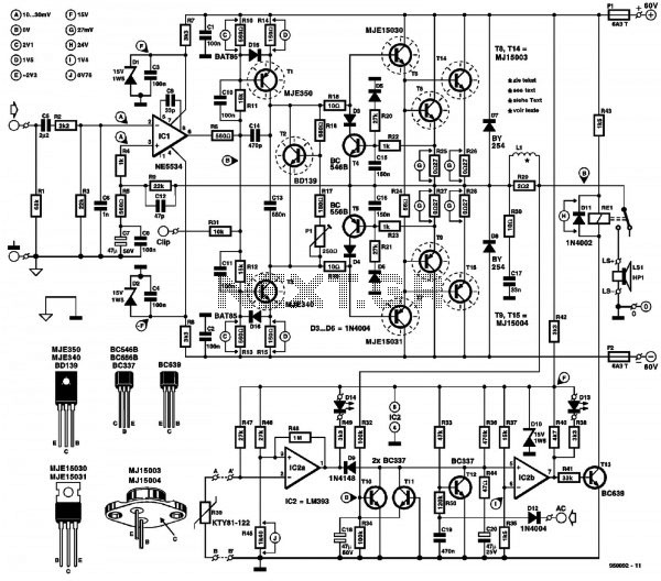
A conventional power amplifier featuring both high-pass and low-pass filters. Powered by a 60V DC supply, this circuit can deliver approximately 300W of sound power. The operational amplifier NE5534 is utilized in the configuration. The described power amplifier circuit integrates...
Here is a simple radio that is easy to build and inexpensive. In fact, you probably have all the parts you need in your junk box. You'll be surprised at the great reception with this little set. More: The...
If a stereo amplifier lacks an input for a record player, it is advisable to utilize this circuit between the turntable and the amplifier. The output from the turntable adheres to a gain-bandwidth curve known as the RIAA compensation...
This 40W fluorescent lamp inverter enables the operation of 40W fluorescent tubes using any 12V source that can provide 3A. It is essentially a larger variant of the 12VDC Fluorescent Lamp Driver and can be utilized to illuminate both...
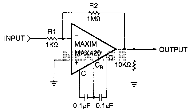
This circuit is a gain-of-1000 inverting amplifier designed to amplify submillivolt signals to levels suitable for further processing. In most system applications, utilizing maximum gain in the MAX420 is advantageous, as it minimizes the effects of offsets in later...
The following circuit illustrates a 5 Zone Anti-Theft Circuit Diagram. This circuit is based on the CMOS 4050B IC. Features: the system may comprise in... The 5 Zone Anti-Theft Circuit utilizes the CMOS 4050B integrated circuit, which is a hex...