
Light intensity 10 a 10LX twilight light control switch circuit diagram
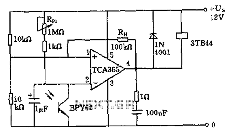
The described circuit employs a bridge input configuration, which is essential for interfacing the phototransistor BPY62 with a power operational amplifier. The BPY62 acts as a light sensor, converting light intensity into an electrical signal. The operational amplifier amplifies this signal to control high power loads effectively. The capacity to handle loads up to 8.5 kW indicates that the circuit is designed for substantial applications, such as industrial lighting or heating systems.
The voltage divider formed by the two 10 kΩ resistors is critical as it establishes a reference voltage at the midpoint, which is necessary for the operational amplifier's functionality. By connecting the inverting input of the operational amplifier to this midpoint, the circuit can achieve precise control over the output voltage, which is inverted to 1/2 Us. This inversion is significant as it allows for the operational amplifier to respond appropriately to varying light levels detected by the phototransistor.
The inclusion of a potentiometer for sensitivity adjustment provides flexibility in the circuit operation, enabling users to calibrate the response based on environmental conditions or specific application requirements. The adjustment range of 10 to 10^4 lx suggests that the circuit can operate effectively across a wide spectrum of light intensities.
Furthermore, the ability to switch resistor sizes impacts the hysteresis loop of the operational amplifier, which is crucial for preventing rapid oscillations or noise in the output signal. This hysteresis feature ensures stable operation by providing a margin of error in the switching threshold.
Lastly, the output circuit's control through a contactor coil indicates that the circuit can engage or disengage high-power loads safely and efficiently. The contactor coil acts as an electromechanical switch, allowing the operational amplifier to control significant power without directly handling high currents, thereby enhancing the overall safety and reliability of the system. As shown with a bridge input circuit phototransistor BPY62 power operational amplifier and can control up to 8.5kW of power load off. Two 10k ohm resistor divider midpoint comp osed of an operational amplifier connected to the inverting input of the amplifier so that the inverted voltage 1/2Us. You can use potentiometer sensitivity adjustment switch within 10 to 10 the fourth lx range. Decided to switch resistors Rh size of hysteresis loops. The output circuit is controlled by the contactor coil.
Related Circuits
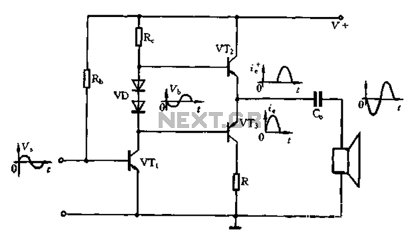
The Class A power amplifier exhibits low distortion; however, it suffers from low efficiency and limited output power, prompting the design of Class B power amplifier circuits. The Class B amplifier operates by shifting the operating point of the...
The circuit comprises two sections: charger power supply and LED driver. The charger power supply section is built around a 3-terminal adjustable regulator (IC1) LM317, while the LED driver section is built around transistor BD140 (T2). In the charger...
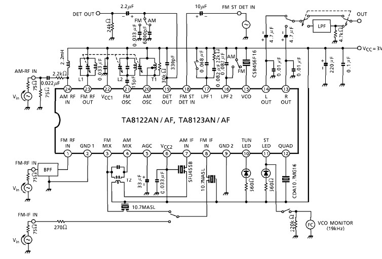
A simple low-power AM/FM radio receiver electronic project can be designed using the TA8122 integrated AM/FM receiver, manufactured by Toshiba Semiconductor. This radio receiver circuit can be utilized for portable radio applications or similar devices. The TA8122 radio receiver...
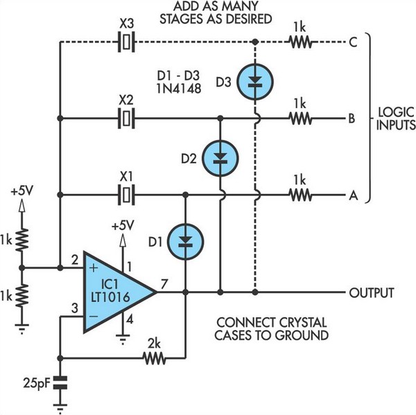
This oscillator circuit allows crystals to be electronically switched by logic commands. To understand the circuit, it is helpful to initially disregard all crystals and consider all diodes as shorts while their associated 1kΩ resistors are treated as open....
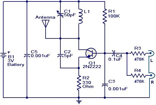
This weblog focuses on electronic circuit schematics, PCB design, DIY kits, and diagrams for electronic projects. The FM transmitter circuit utilizes the NPN transistor 2N2222. The inductor L1 and capacitor C1 generate the necessary oscillations for Q1. The collector...
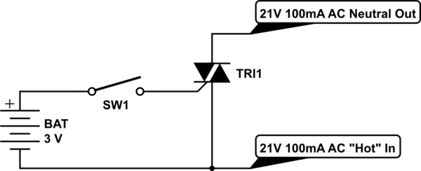
Control a furnace using a 3.3V microcontroller. The furnace operates by connecting a common 21V AC "hot" line to one of two AC "neutral" output lines: Fan and Heat. When connected, they have relatively low current flow, approximately 100mA....
Warning: include(partials/cookie-banner.php): Failed to open stream: Permission denied in /var/www/html/nextgr/view-circuit.php on line 713
Warning: include(): Failed opening 'partials/cookie-banner.php' for inclusion (include_path='.:/usr/share/php') in /var/www/html/nextgr/view-circuit.php on line 713