
Op-Amp Pulse Generator Circuits
The operational amplifier-based square wave oscillator circuit utilizes the principles of feedback, integration, and hysteresis to generate a stable square wave output. The comparator section of the circuit, formed by the operational amplifier, compares the voltage at its non-inverting input with a reference voltage set by the resistors R2 and R4. The introduction of hysteresis through these resistors prevents rapid toggling of the output due to noise or minor fluctuations in the input signal, thereby enhancing the stability of the oscillation.
The integrator section, consisting of capacitor C and resistor R1, plays a critical role in shaping the waveform. As the output of the comparator switches states, the integrator charges and discharges, producing the characteristic exponential rise and fall of the voltage across the capacitor. The time constants for charging and discharging, determined by the resistor-capacitor (RC) values, set the frequency of oscillation. The derived frequency equation, F = 0.7 / (R1 x C), illustrates the inverse relationship between frequency and the product of R1 and C, indicating that increasing either component value will reduce the frequency of oscillation.
In circuits where separate charging and discharging paths are employed, the duty cycle can be manipulated by adjusting the values of resistors R1 and R2. This allows for the generation of pulse trains with varying high and low durations, expanding the versatility of the oscillator design. The choice of components, including the operational amplifier, is crucial for achieving desired performance characteristics, such as power consumption and output frequency range.
Overall, the operational amplifier-based square wave oscillator is a fundamental circuit design that demonstrates key principles of analog electronics, including feedback control, timing, and waveform generation. Its adaptability and ease of implementation make it a valuable tool in various applications, from signal generation to clock pulse creation in digital circuits.A number of operational amplifier circuits are provided here that are set up to be squarewave oscillators. A squarewave is a Periodic Wave pulse train with a 50 percent duty cycle. The operational amplifier is really just a high-gain amplifier, so oscillation is not a problem with just a little positive feedback [R4 provides the positive feedback
in the first schematic]. This style oscillator is formed by three separate pieces or functions; a comparator made up of the Op-Amp, an integrator formed by the capacitor and R1, and a latch formed by resistors R2 and R4 [which adds hysteresis to the comparator]. The amplifier oscillates based on the voltage applied to the V+ line, which is used to change the set point.
Resistor R3 helps with bias current and could be removed. The exponential voltage which develops across the capacitor is converted to a current by resistor R1. The rising and falling exponential voltage is set by the product of the resistor capacitor combination.
The frequency of oscillation is determined by the following equation: F = 0. 7 / (R1 x C). The period would than be 1. 4*(R1 x C). Because only one timing path exits, the capacitor changes and discharges though the same resistor, the circuit produces a square wave. the trip points, when the oscillator switches, is set by the comparator input which is determined by V+, R2 and R4.
In most cases R2 is made equal to R4. This example of a square wave oscillator uses an LM124, a low power quad amplifier. Only one amplifier in the package is being used, so the other unused devices should be tied off. The output of an unused Op-Amp should be tied to the minus input, and the plus input should be left open [unconnected]. A rectangle wave is a squarewave with something other than a 50 percent duty cycle. A pulse train is a term used when the duty cycle is either very high or very low, resulting in a recurring narrow pulse.
This circuit is identical to the first oscillator except now there is an individual charging path for the capacitor and a discharge path that each use different resistor values. Charging the capacitor is through the diode and Resistor R2, while discharging the capacitor is done through the opposite diode and resistor R1.
The high portion of the output pulse is determined by C*R1, and the low portion of the pulse is controlled by C*R2. Yet another variation, but this time the circuit only requires one diode. Again, the LM124 is just an example one Op-Amp. The component values don`t change based on which operation amplifier is being used. These circuit designs operate off the [exponential] changing and discharging time of a capacitor and resistor.
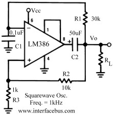
So care needs to be taken when selecting timing values and voltage trigger points, as the charging time is non-linear. Another operational amplifier designed as a square wave oscillator is the LM386, a low power audio amplifier [shown in the right side-bar].
The schematic is provided because it differs from the other examples, but it was extracted from some data sheet just like the other circuit examples. No details are provided, other than example component values and the output frequency. It should be noted that these circuit designs have been around since the 1970`s and published in many different books and application notes.
The general design works for almost any operational amplifier, so what Op-Amp data sheet they end up in is just random chance, or what company data sheet they end up in. 🔗 External reference
Related Circuits
Descriptions of the various modules in a home-built music synthesizer - Sub-oscillator project. The sub-oscillator module in a home-built music synthesizer serves a crucial role in enriching the sound by generating lower frequency signals that complement the primary oscillators. This...
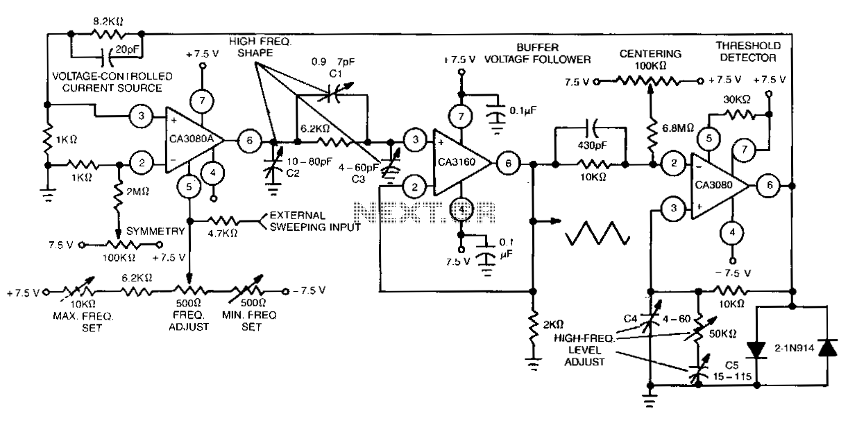
This function generator features an adjustment range exceeding 1,000,000 to 1 and utilizes a CA3160 BiMOS operational amplifier as a voltage follower. It incorporates a CA3080 operational transconductance amplifier (OTA) as a high-speed comparator, alongside another CA3080 configured as...
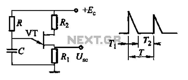
Common non-sinusoidal oscillator circuit, waveform and frequency formula - pulse wave oscillator - blocking oscillator transformer The common non-sinusoidal oscillator circuit is designed to generate pulse waveforms, which are characterized by their square or rectangular shape. These oscillators are...
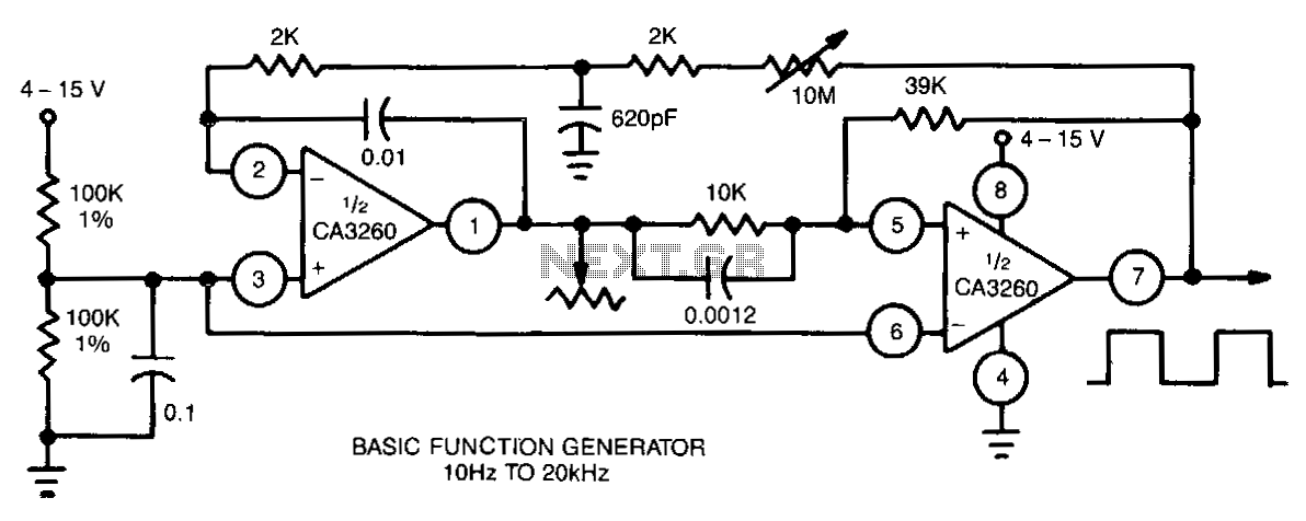
This function generator utilizes a CA3260 BiMOS operational amplifier to perform both integrator and switching functions. A 620-pF capacitor and a 2-kΩ resistor are employed to shape the feedback square wave, minimizing spikes. The device covers the full audio...
This type of design can produce a very high amperage current for a fraction of a second that can be used to do some useful work if properly harnessed. The switching device could be a rotating spark gap as...
The basic two-transistor flasher has become widely utilized in various applications due to its simplicity and versatility. It has been employed in circuits such as a micropower low battery indicator, a lightning detector, an off-line switching power supply, a...
Warning: include(partials/cookie-banner.php): Failed to open stream: Permission denied in /var/www/html/nextgr/view-circuit.php on line 713
Warning: include(): Failed opening 'partials/cookie-banner.php' for inclusion (include_path='.:/usr/share/php') in /var/www/html/nextgr/view-circuit.php on line 713