
Flasher Circuits
The two-transistor flasher circuit is a fundamental design in electronics that leverages the properties of transistors to create an oscillating effect. The circuit consists of two transistors, typically a PNP and an NPN, configured in a feedback loop with a capacitor and resistors. The PNP transistor is responsible for initiating the charging of the capacitor, while the NPN transistor acts as a switch that controls the discharging process.
To construct the circuit, the PNP transistor's base is connected to a voltage divider formed by two resistors, which sets the threshold voltage for activation. The capacitor is connected to the collector of the PNP transistor, and its charging path includes the battery voltage. As the capacitor charges, it reaches a point where the voltage across it exceeds the threshold set by the base resistors, turning on the PNP transistor.
Once the PNP transistor turns on, it allows current to flow through the NPN transistor, which also turns on due to the feedback from the PNP. This simultaneous conduction of both transistors leads to a rapid increase in current, which causes the voltage across the circuit to drop. The drop in voltage further reduces the threshold, creating a feedback loop that keeps both transistors in the 'on' state until the capacitor discharges below a certain level.
To enhance the circuit's functionality, additional components can be integrated. For example, using a power transistor or FET can increase the current handling capability, making the circuit suitable for driving larger loads such as lamps or motors. The addition of a diode in series with the capacitor charging resistor can prevent reverse current flow during discharge, effectively extending the on-time of the circuit.
In applications like a low battery indicator, the circuit can be calibrated to activate at a specific voltage level, providing a visual alert when battery voltage drops below a predetermined threshold. This is achieved by adjusting the resistor values in the voltage divider and selecting an appropriate zener diode.
Overall, the two-transistor flasher circuit exemplifies a versatile and adaptable design that can be tailored to various electronic applications, showcasing the fundamental principles of transistor operation and feedback mechanisms in circuit design.The basic two-transistor flasher shown below has found its way into dozens of applications due to its simplicity and versatility. Applications have included such diverse circuits as a micropower low battery indicator, a lightning detector, a off-line switching power supply, a micropower high voltage supply, an unusual beeping capacitance probe,
a windshield wiper controller, a lamp dimmer, a police siren, and several others. The simple circuit can be used at very low frequencies, RF frequencies, low voltages, or even very high voltages with careful selection of transistors. The power handling capability and power consumption are also easily modified to suit the requirement.
The basic flasher is shown below. Notice that it is a "two-wire" circuit and simply connects in series with the load and battery. The two resistors on the base of the PNP set a threshold voltage and when power is applied the capacitor begins charging toward this voltage. When the capacitor voltage is high enough the two transistors begin to conduct. The current flow causes the voltage across the circuit to drop slightly and this drop causes a drop in the threshold voltage.
The lower threshold voltage causes even more current and this positive feedback causes the circuit to rapidly turn on. It stays on until the capacitor discharges at which point a reverse process causes the circuit to suddenly switch off.
Power transistors may be added for handling higher current loads. The two circuits below are typical connections. In the first circuit a flasher circuit in series with a 220 ohm resistor turns on a power transistor. In the second circuit, a power FET is used in place of the NPN. A pull-down resistor is added to pull the gate low when the circuit turns off. Don`t hesitate to modify this basic circuit to meet your specific requirements. It is easy to troubleshoot and almost always works! Here are a few more ideas for the experimenter to try: A diode may be inserted in series with the capacitor charging resistor so that discharge current is blocked which gives a longer "on" time for a given flash rate.
The NPN base resistor determines how fast the capacitor discharges. The PNP base divider resistors can be adjusted so that the voltage is just a little too high for a flash to occur when the capacitor fully charges. Then, a very tiny AC signal applied to the base will cause the circuit to "trigger". The frequency response of this detector can be surprisingly high. The circuit below is a "silent" metronome that keeps the beat without becoming a member of the band. The circuit flashes the 6 volt lamp at a rate set by the 20k potentiometer which can have a dial for setting the desired tempo.
Alternately, the potentiometer could be replaced with a rotary switch and selected resistors. The lamp is an ordinary #47 bulb which will give good omni directional brightness but an LED and resistor could be used instead - try a 100 ohm in series with a high-intensity LED. The batteries could be three C or D cells for good life. This circuit could be used to generate "clicks" in a speaker but such metronomes are not particularly pleasing.
The ambitious might replace the lamp with a solenoid which taps on the wall of a hardwood box or wooden chime for a "professional" sound. Here is a low battery indicator that flashes a lamp when the battery voltage falls below about 5 volts.
The circuit draws about 25 microamps when not flashing so battery life is not significantly shortened by the circuit. The two 1 megohm resistors set the switching point at V/2 (plus a little due to the emitter-base diode drop) and when this voltage is above the zener voltage the circuit cannot turn on.
When the battery voltage drops below 5 volts, the base voltage drops to 2. 5 volts and the emitter can reach a voltage sufficient to turn on the PNP (2N4403 or similar). When the PNP conducts, the NPN also conducts dropping the voltage acros 🔗 External reference
Related Circuits
This project flashes eight LEDs in a seemingly random manner. It utilizes a 4026 combined counter and display driver integrated circuit (IC) designed for driving 7-segment LED displays. The sequence is not entirely random, as seven of the LEDs...

This is a compact LED flasher circuit designed using the 555 timer integrated circuit (IC), powered by two 1.5V batteries. The circuit can function as a flashing metronome, dark room timer, reminder, or for other similar applications. In the...

This is a diagram of a car audio active loudspeaker utilizing the LF353 operational amplifier from National Semiconductor. For optimal performance, the NE5532 is recommended to split the audio signal into three frequency bands using an active filter. The...

A 555 four-base integrated circuit delay circuit is designed to facilitate a transition from high to low output. When the button SB is pressed, the output is set to high, and after a specified delay, the output transitions to...
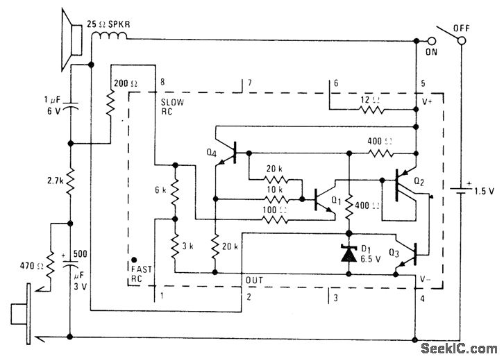
A low-drain circuit powered by a 1.5-V cell utilizes the National LM3909 flasher IC to simulate a fire-alarm siren. Pressing a button generates a rapidly increasing wail, with the tone decreasing in frequency once the button is released. The...
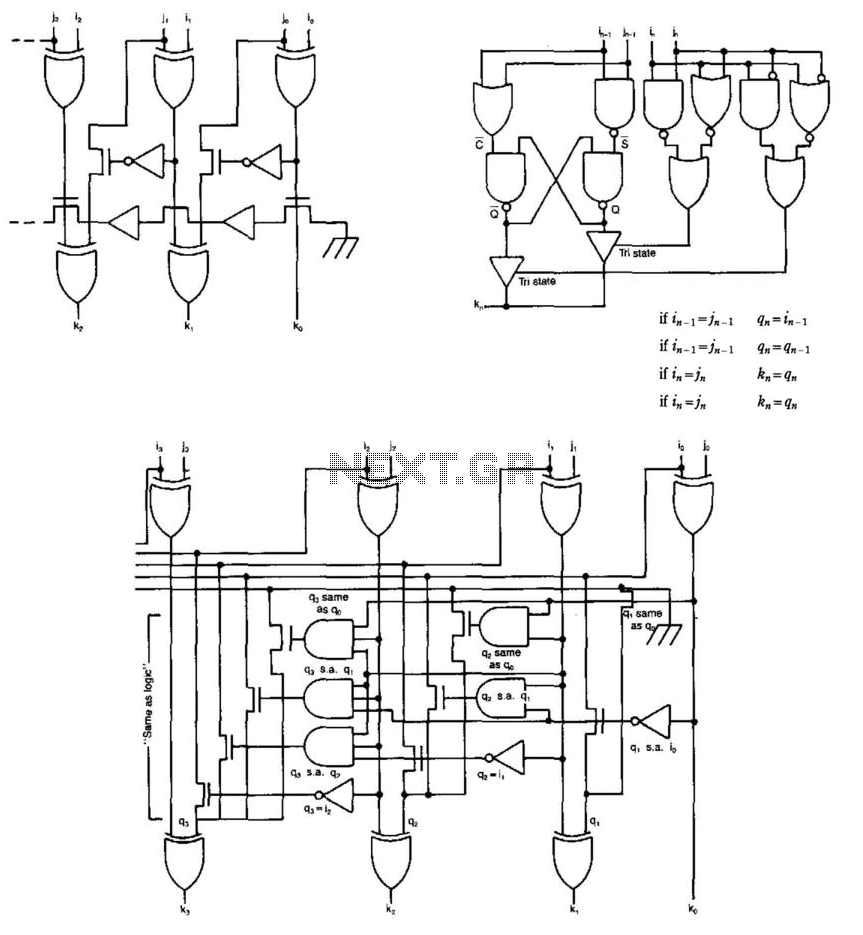
Some circuits that add binary numbers experience time delays due to carry propagation. This issue has been partially addressed by the carry look-ahead adder. However, the complexity of this method typically limits its application to no more than 4...