
Common non-sinusoidal oscillator circuit waveform pulse wave oscillator blocking oscillator transformer
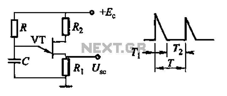
The common non-sinusoidal oscillator circuit is designed to generate pulse waveforms, which are characterized by their square or rectangular shape. These oscillators are essential in various electronic applications, including clock generation, signal modulation, and timing circuits. The pulse wave oscillator operates by utilizing a feedback mechanism that allows the circuit to switch between high and low states rapidly, resulting in a periodic output waveform.
The frequency of the pulse waveform generated by a blocking oscillator can be determined using specific formulas that take into account the values of the circuit components, such as resistors, capacitors, and inductors. In a typical blocking oscillator configuration, a transformer is employed to provide feedback to the transistor or active device, enabling it to oscillate. The frequency of oscillation is influenced by the inductance of the transformer and the capacitance in the circuit.
The output waveform of a pulse wave oscillator can be visualized as a series of sharp transitions between the high and low voltage levels, with a duty cycle that can be adjusted based on the circuit design. The duty cycle is defined as the ratio of the time the output is in the high state to the total period of the waveform. This characteristic makes pulse wave oscillators particularly useful in applications where precise timing and control of signal duration are required.
In summary, the common non-sinusoidal oscillator circuit, specifically the pulse wave oscillator and blocking oscillator transformer configuration, is a fundamental component in electronic design, providing essential timing and waveform generation capabilities. Understanding the underlying principles and formulas governing these circuits is crucial for engineers working in the field of electronics. Common non-sinusoidal oscillator circuit, waveform and frequency formula - pulse wave oscillator - blocking oscillator transformer
Related Circuits
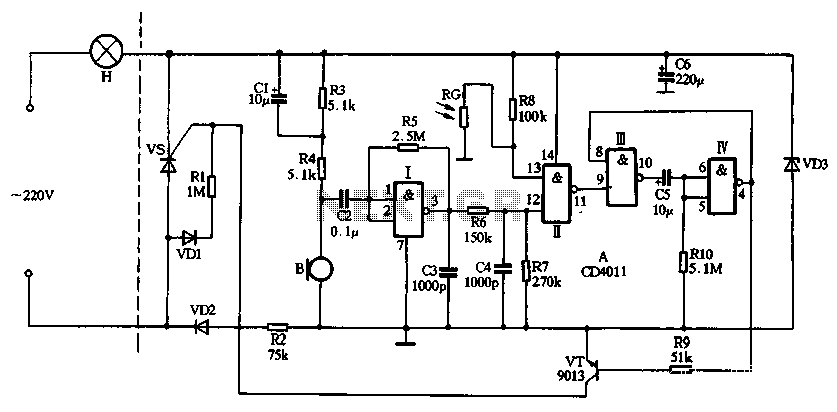
This light alarm schematic circuit is designed using common electronic components, as illustrated in the circuit diagram below. The light alarm circuit will activate an alarm as soon as the drawer is opened and light falls on the Darlington...
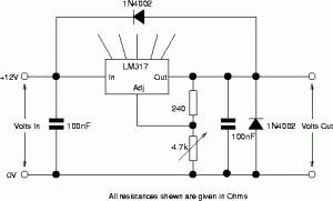
The following circuit illustrates the circuit diagram of a motor control unit. This circuit is based on the LM317 integrated circuit. Features include diodes that protect the regulator. The motor control unit circuit utilizes the LM317 voltage regulator to provide...
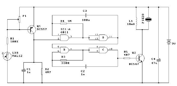
The circuit utilizes CD4011 digital circuits to create a sound-activated light lamp with a dual-control delay section. The left portion of the circuit represents the lighting lines, while the right part consists of the sound and light control delay...
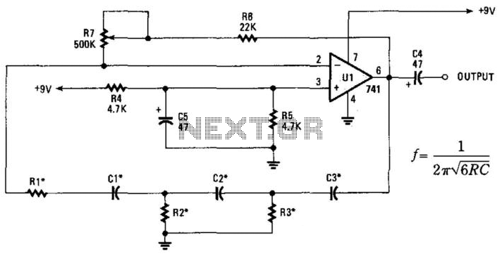
This phase-shift oscillator is suitable for audio oscillator applications. Adjust R7 to achieve a good sine wave. An amplifier gain of 29 is necessary for oscillation. If C=C1=C2=C3 and R=R1=R2=R3: Typically, R will range from 1 to 100 kOhm...
This circuit was designed to drive an impact counter, utilizing the ICL8038 as its core component. It is intended for a motor that operates a conveyor, with the motor featuring a feedback system known as a tachogenerator. Only a...
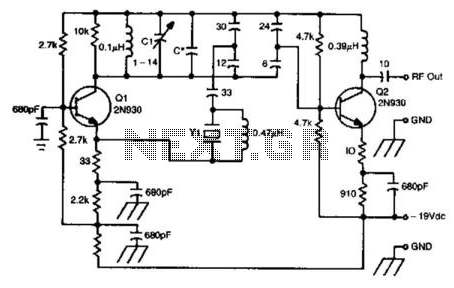
This oscillator circuit utilizes a 5th overtone crystal operating within the 85 to 106 MHz frequency range. The component Y1 represents the crystal. The circuit was initially designed for frequency control in a microwave oscillator. The oscillator circuit leveraging a...