
op amp square wave generator
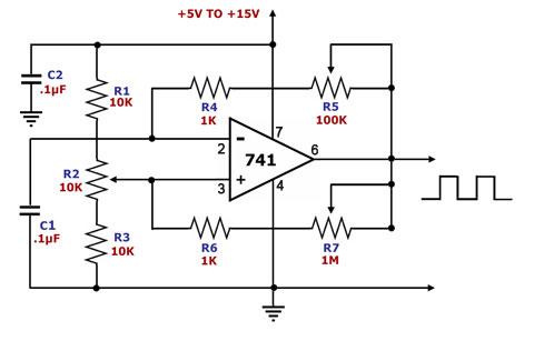
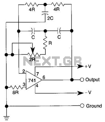
The square wave generator circuit utilizes the 741 operational amplifier in a configuration that allows for the generation of a square wave output. The circuit's performance is influenced by the selection of timing components, specifically the capacitor C1 and the resistors R4, R5, R6, and R7, which define the frequency of oscillation. The resistors R1, R2, and R3 are responsible for setting the duration of the high and low states of the output waveform, thus controlling the duty cycle.
To achieve pulse symmetry, it is important that the resistance to ground from pin 3 of the op-amp is equal to the resistance to Vs. This balance ensures that the transitions between high and low states are consistent and results in a symmetrical square wave. For applications requiring precise symmetry, it is recommended to replace the resistors R1, R2, and R3 with two equal resistors connected to the output pin. One resistor connects to the positive supply voltage (Vs), while the other connects to ground, effectively creating a voltage divider that maintains symmetry in the output waveform.
The circuit can be powered by a single supply voltage, simplifying the design and reducing component count. The adjustable nature of the output frequency and duty cycle makes this square wave generator suitable for various applications, including clock signals for digital circuits, timing applications, and waveform testing. Proper selection of the timing components allows for fine-tuning of the output characteristics, making it a versatile tool in electronic design and experimentation.This is a square wave generator circuit. The main component of this circuit is the 741, a general-purpose operational amplifier. This circuit employs a single power supply Vs that can range from +5V to +15V. The square wave output of this circuit is easy to adjust. `Timing` is defined by C1, R4, R5, R6, and R7 while duration is defined by R1, R2, and R3. Pulse symmetry is achieved by making the resistance from pin 3 to ground equal to the resistance from pin 3 to Vs. If this is desired, then R1, R2, and R3 may simply be replaced by two equal resistors from pin 3, one of which is tied to Vs while the other is tied to ground.
🔗 External reference
Related Circuits
This circuit is designed to serve as a reliable substitute for thermally-activated switches used in Christmas tree lamp-flashing applications. The configuration comprising Q1, Q2, and associated resistors activates the SCR. Timing is managed by R1, R2, and C1. To...
This FM RF power amplifier circuit is constructed using a BLY94 transistor, which can deliver up to 50W at a frequency of 175MHz with a power gain of 7dB, resulting in approximately 5 times power amplification. However, in this...
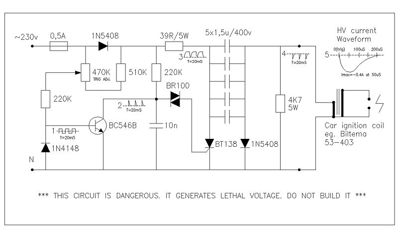
This circuit generates high voltage pulses from a 230 VAC line voltage. The drive end's swing comparator circuit was developed by the creator of this page. The working end is derived from a stroboscope trigger supply circuit. All circuits...
Here is a little audio amplifier similar to what you might find in a small transistor radio. The input stage is biased so that the supply voltage is divided equally across the two complimentary output transistors which are slightly...
The quality of the sine wave depends on how closely the components in the twin-T network are matched in the operational amplifier's feedback loop. The twin-T network is a type of filter circuit commonly used in audio applications, signal processing,...
The TDA8932B/33(B) can operate with a symmetrical power supply. In this configuration, three half supply voltage buffers are disabled when powered from a symmetrical source. The TDA8932B/33(B) is a high-efficiency Class D audio amplifier designed for various audio applications. Operating...