
Photoelectric counting circuit diagram
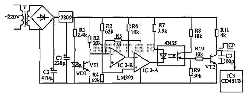
The described circuit functions as an object detection system utilizing infrared light transmission and reception. The primary components include an infrared light-emitting diode (VD1), a phototransistor (VT1), comparators (IC2-A and IC2-B), an optocoupler (4N35), and a secondary transistor (VT2) for signal processing.
Upon activation, the infrared LED emits light that is continuously monitored by the phototransistor. The circuit is designed to detect interruptions in the infrared beam caused by physical objects passing between the emitter and the receiver. When the beam is unobstructed, the phototransistor remains conductive, maintaining a low output at the comparator IC2-A, which keeps the optocoupler and VT2 activated.
The logic of the circuit relies on the behavior of the comparators, which compare input voltages and determine the output state based on the presence or absence of infrared light. The transition from low to high output at the collector of VT2 serves as a pulse signal, which is essential for counting events (i.e., the passing of objects). This pulse signal can be processed further by a decimal counter, which accumulates counts and sends the data to a display circuit for visual representation.
In summary, the circuit effectively monitors the presence of objects using infrared technology, allowing for applications in automation, counting systems, or security monitoring. The design emphasizes reliability and responsiveness, making it suitable for various electronic applications that require object detection and counting. Circuit shown in Figure, when the phototransistor VT1 receives infrared light-emitting diode to the infrared light emitted, VT1 conduction, the inverting input of the comparato r IC2-B 6 feet low end, 7 feet high output, applied to the comparator IC2-a inverting input terminal, so that a pin output low, the optocoupler LEDs light 4N35 within the corresponding photodiode is turned on, the transistor VT2 are conduction, VT2 collector output low. When an object passes between the infrared light-emitting diodes VD1 and receiver tube VT1, infrared rays are blocked, VT1 off, 1 foot high output of IC2-A, 4N35 off, VT2 off, VT2 collector output high, so when there is when an object by VT1, VT2 collector output on it counted pulse signal which is sent to a decimal counter, then sent decoding display circuit, showing corresponding data.
Related Circuits
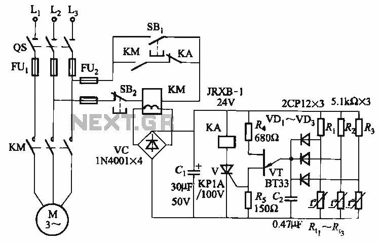
The thyristor control circuit includes a bridge circuit designed to regulate the temperature in the contactor coil KM, along with a secondary winding that functions as a power protection device. It comprises a thermistor (R:., Rt3) and a resistor...
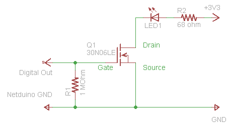
The process of driving an LED involves using a Power MOSFET to control the LED's state (On and Off) via a digital signal. This guide provides a step-by-step approach to wiring the circuit on a breadboard, which serves as...
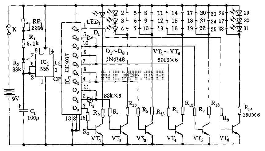
The circuit features a clock pulse generator and a pulse distribution circuit that drives the display circuit. It consists of a 555 timer and resistors RP1, R1, R2, along with capacitor C1, forming an astable multivibrator. The oscillation frequency...
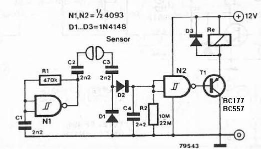
The liquid detector is a device designed to detect the presence of liquid using alternating voltage. This circuit can be constructed using common electronic components. The alternating voltage is generated by a gate with a Schmitt trigger function, acting...
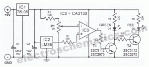
Measuring the temperature of coffee is important because the taste of coffee relies on two main factors: the strength of the coffee and its temperature. Measuring the temperature of coffee can be accomplished using a simple electronic circuit designed to...
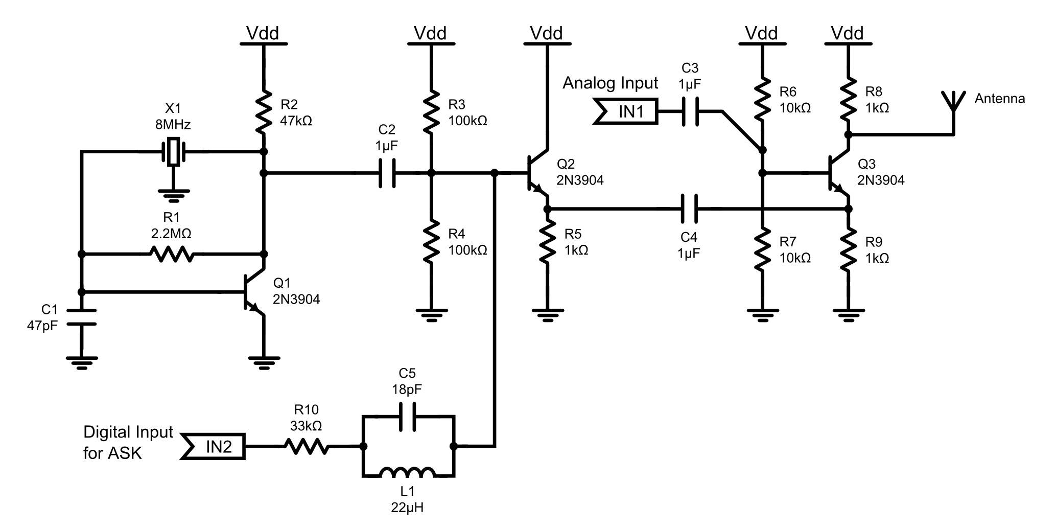
This is an 8MHz amplitude modulated (AM) radio transmitter designed primarily for practical applications and as an educational exercise in electronics. The objective was to create a simple radio transceiver that could be used in future projects requiring basic...
Warning: include(partials/cookie-banner.php): Failed to open stream: Permission denied in /var/www/html/nextgr/view-circuit.php on line 713
Warning: include(): Failed opening 'partials/cookie-banner.php' for inclusion (include_path='.:/usr/share/php') in /var/www/html/nextgr/view-circuit.php on line 713