
Vu meter stereo circuit

The circuit utilizes the LM3915, a versatile LED bar graph/LED dot display driver, which can operate in two modes: bar mode and dot mode. In bar mode, the LEDs display a continuous level, while in dot mode, only one LED is illuminated at a time, corresponding to the input signal level. The CA3130, a precision op-amp, is used to process the audio signal, ensuring that it is amplified and rectified before being fed into the LM3915. This combination allows for a visual representation of audio levels, making it ideal for audio applications such as VU meters.
To implement this circuit, the LM3915 is connected to a series of 10 LEDs, each representing a different level of audio signal strength. The CA3130 is connected to the audio source, with its output linked to the input of the LM3915. The trimmer resistor R1 is crucial for calibration, allowing fine adjustments to ensure that the meter accurately reflects the 0dB level. The jumper configuration offers flexibility in display style, enabling users to choose between a dot or slash indication based on their preference or application requirements.
This circuit can be effectively used in audio mixing consoles, sound level meters, or any electronic device where audio level monitoring is necessary. The simplicity of the design, combined with the functionality of the LM3915 and CA3130, makes it a valuable tool for both amateur and professional audio engineers. Proper assembly and calibration will yield a reliable and visually informative audio level indicator.This simple circuit is based on the well-known integrated circuit LM3915. The main characteristic of this integrated circuit is its power to manage 10 LED-s (Light Emitting Diodes) in logarithmic scale with a difference between the 3dB LED-s, which it can turn on the slash or on the dot . The other integrated circuit, the CA3130 is in charge of amplifying and rectifying the audio signal to the entrance of LM3915. To adjust the vu-meter to 0dB, we can download any free programme for Windows which will generate BF, , for example, which doesn`t even need to be installed. With the exit adjusted to 1000 Hz and 0dB in the sine mode, we shall move the trimmer R1 until the seventh led of our assembly is lit on, and it will correspond with 0dB.
If we wish the LED-s to turn on the slash , we`ll have to short-circuit the jumper of the circuit marked as B/P. When the jumper is open, the LED-s are lit on the dot , one by one. 🔗 External reference
Related Circuits
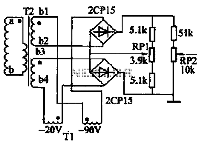
The closed-loop system consists of longitudinal and transverse components. The circuit operates as follows: a control circuit from the stepping motor CNC system issues a command, which the receiver detects. This signal is processed through a phase-sensitive rectifier to...
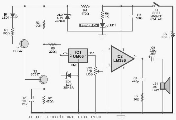
This infrared detector is capable of detecting the presence of modulated infrared signals in its vicinity from various electronic sources, such as an IR handheld remote. The infrared detector operates by utilizing a photodetector that is sensitive to infrared light....
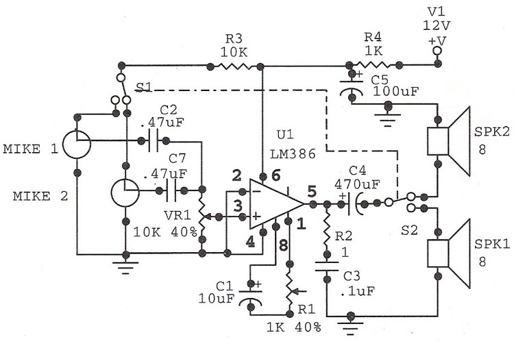
The LM386 is an ideal choice for a door phone application. This device is particularly beneficial in modern urban households, utilizing a condenser microphone and a speaker. The LM386 is a low-voltage audio power amplifier that is commonly used in...

The circuit utilizes a three-terminal adjustable integrated voltage regulator. It includes a gear set and a power supply voltage that is stepped down using a transformer rated at 17.5V x 2 AC. The output voltage after the bridge rectifier...
Battery Volt Meter Circuit Diagram. This circuit is designed to monitor the voltage level in Lead Acid or Tubular batteries. It provides four LED indicators to represent the voltage levels ranging from 9 volts to 14 volts. The battery voltmeter...
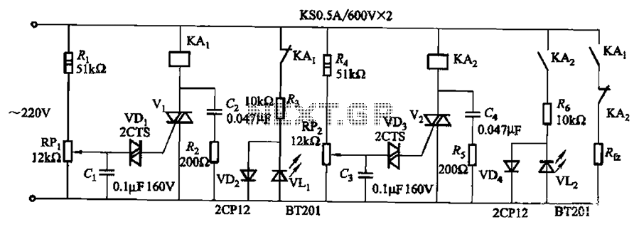
Bidirectional thyristor control. By adjusting potentiometers RPi and RPz, the lower and upper limit values can be changed. LEDs VLi and VL2 serve as indicators for low pressure and high pressure, respectively. The circuit utilizes a bidirectional thyristor to control...