
OPA606 capacitive load isolation buffer

The isolation buffer circuit is designed to enhance the performance of circuits that need to drive capacitive loads, which are often challenging due to stability issues. The OPA606 operational amplifier is selected for its high input impedance and low output impedance, which minimizes the loading effect on the preceding stage. This amplifier's FET input ensures a wide bandwidth and low noise, making it suitable for high-frequency applications.
The RC compensation network, consisting of the resistor R1 and capacitor C1, plays a critical role in stabilizing the circuit. The 10kΩ resistor helps to limit the current and sets the gain of the buffer stage, while the 20pF capacitor provides phase compensation, which is essential for maintaining stability when driving capacitive loads. Together, these components form a feedback loop that mitigates potential oscillations and ensures a smooth transient response.
In practical applications, this isolation buffer circuit can be employed in sensor interfacing, analog signal conditioning, and other scenarios where capacitive loads are present. The design allows for a robust response to varying load conditions while preserving signal integrity, making it a valuable addition to any electronic system requiring reliable performance under capacitive loading. As shown for the isolation buffer circuit capacitive load. Usually when an external op amp for capacitive load, will seriously affect the stability of the circuit, while its dy namic performance will be severely degraded, and was able to better illustrated circuit driving a capacitive load, because the circuit uses a FET input type dielectric isolation wideband operational amplifier OPA606 composed isolation amplifier, and amplifying circuit with a carrying capacity tends to idealize. The reason why this circuit has such a good load capacity, due to the OPA606 has its own characteristics and the external circuit of the RC compensation network.
The figure shows the resistance of the access circuit is 10k resistor R1 and the compensation capacitor C1 (with a capacity of 20pF).
Related Circuits
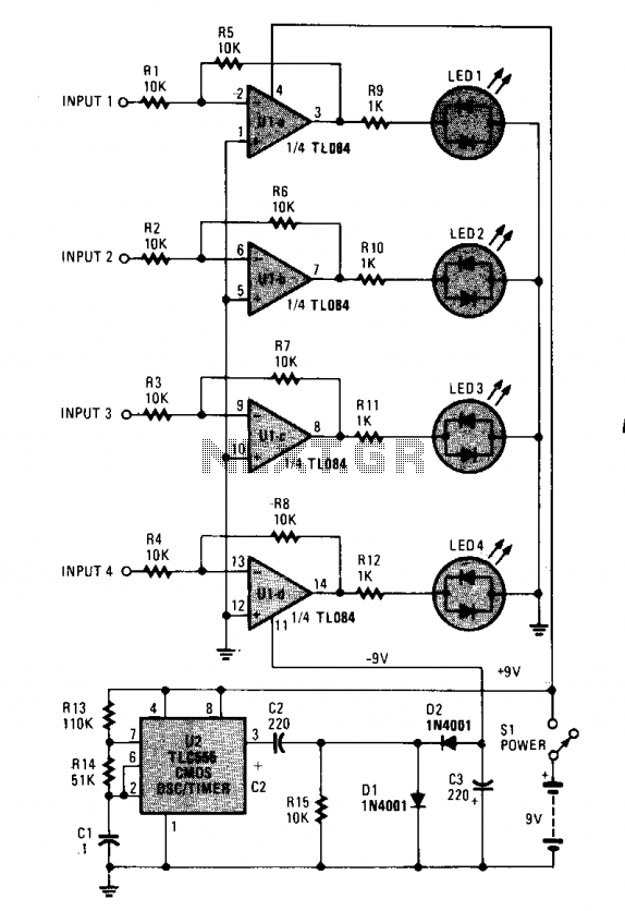
The monitoring circuit consists of four tri-color LEDs driven by an equal number of operational amplifiers configured as inverting amplifiers with a gain of one. Each LED is wired such that it illuminates red when the input to the...
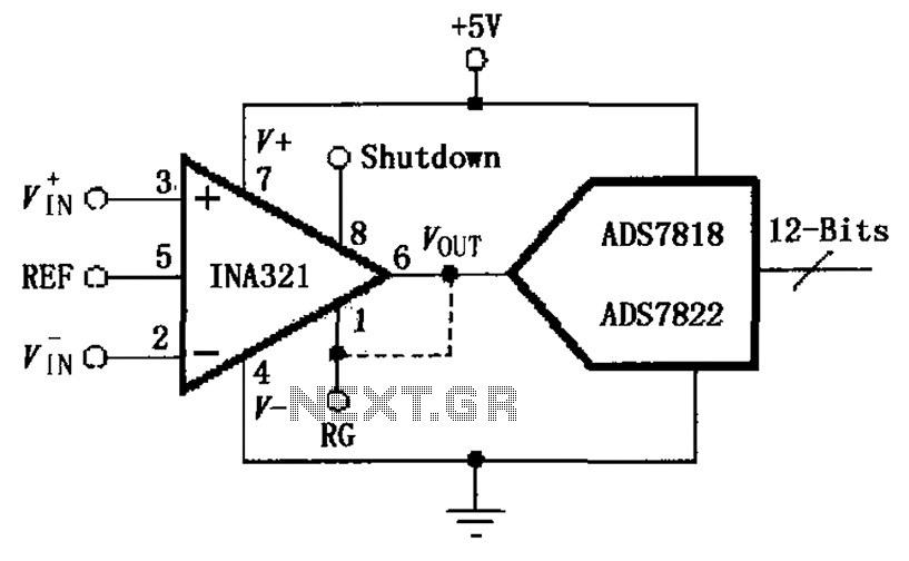
The INA321/322 is configured to directly drive the capacitive input of an A/D converter. Due to its low output resistance, the INA321/322 can effectively handle high frequency signals and directly drive capacitive loads. The input voltage is amplified by...
These are circuits of high impedance low capacitance buffer and high impedance low capacitance amplifier. The first figure is a high impedance low capacitance. High impedance low capacitance circuits are critical in various electronic applications, particularly in signal processing and...
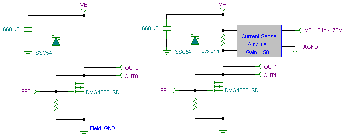
The PWM pulse width modulation controller board enables 9S12/HCS12 microcontrollers or PIC microcontrollers to output 8 channels, each capable of delivering 5 DC amps, while incorporating current sensing for the PWM waveform. This PWM driver circuit is suitable for...
The load described here is capable of handling up to 10 watts of RF power for a couple of minutes and is designed for the widely used 50 ohms impedance. It consists of ten parallel connected 560 ohms 1...
This circuit utilizes a photoelectric coupler to achieve 100GΩ isolation between a TTL (Transistor-Transistor Logic) circuit and a relay circuit. This configuration effectively prevents relay noise and peak voltage from affecting the TTL circuit. When the TTL input signal...