
RF Dummy load

The RF dummy load circuit serves as an essential component for testing and tuning RF transmitters by providing a stable load while minimizing reflected power. The configuration employs ten 560-ohm resistors connected in parallel, which effectively reduces the total resistance to 50 ohms, ideal for most RF applications. To accommodate higher power levels, the design flexibility allows the substitution of resistors with higher wattage ratings or increasing the number of resistors to maintain the desired impedance.
The voltage divider formed by resistors R11 and R12 is critical for measuring the output voltage, which correlates to the RF power being dissipated in the load. The rectifier circuit, composed of diode D1 and capacitor C1, converts the RF signal into a DC voltage that can be easily read by a voltmeter. The choice of a Schottky diode is advantageous due to its low forward voltage drop and fast switching capabilities, which are essential for accurately capturing the RF voltage levels.
The physical construction of the dummy load is designed to minimize parasitic inductance and capacitance, which could affect performance. The use of a tin can enclosure not only provides a sturdy housing for the components but also aids in heat dissipation, ensuring that the resistors can handle the thermal load generated during operation without compromising performance. Care should be taken to avoid drilling ventilation holes, as this could lead to radiation losses, negating the dummy load's effectiveness.
Calibration of the voltmeter against a known reference, such as a professional RF wattmeter, is recommended to ensure accurate measurements across various power levels. The resulting data can be plotted to create a calibration curve, allowing for precise determination of RF power output based on the voltmeter readings. Overall, this dummy load represents a practical solution for RF testing, offering reliability and adaptability for various power levels and applications.The load described here is capable of handling up to 10 watts of RF power for a couple of minutes, and is designed for the widely used 50 ohms impedance. It consists of ten parallel connected 560 ohms 1 watt resistors, R1 through R10, a voltage divider, R11-R12, and a rectifier D1-C1.
Apart from loading the transmitter output with a minimum of reflected power, the dummy load also provides a direct voltage output to which a voltmeter may be connected to measure the RF power. If the dummy load is used for power levels higher than 10 watts simply use more, or higher wattage resistors to give a total of about 50 ohms.
For instance, by using twenty 2 watt 1,200 ohms resistors instead of R1-R10 and 150 ohms resistors for R11 and R12, the dummy load is turned into a 40 watt version. The diode may be almost any Schottky type. Types like BAT85 and HSCH1001, for instance, are also suitable. Even a germanium type like the AA119 will work, but then for low powers only. The dummy load is housed in a tin can of which the cover is used to mount the components. As illustrated, the ten 560 ohms resistors are soldered in a circlearound the center pin of the BNC socket. Their ground terminals are soldered flush to the inside of the cover. Capacitor C1 is a feed through type for which a small hole must be drilled in the cover. All resistors should be mounted with the shortest possible lead lengths to keep the reactive component of the dummy load as small as possible.
After mounting the parts, the cover is fitted on to the tin can again, and soldered all around to seal the dummy load completely. Do not drill ventilation holes in the tin can because that will defeat the purpose of making a non-radiating load.
The can may get quite hot when transmitter power is applied for a while, but that is no cause for concern. The voltmeter read-out produced by the dummy load may be calibrated against a professional RF voltmeter (for instance a 'real' Bird Thruline).
The voltages obtained at differebt RF power levels are noted so that a graph can be made. Depending on the reactive characteristics of the resistors used, the dummy load should exhibit a VSWR of less than 1.5 for frequencies up to 450 MHz. Resistors R13 may be omitted if the dummy load is always used with same voltmeter. 🔗 External reference
Related Circuits
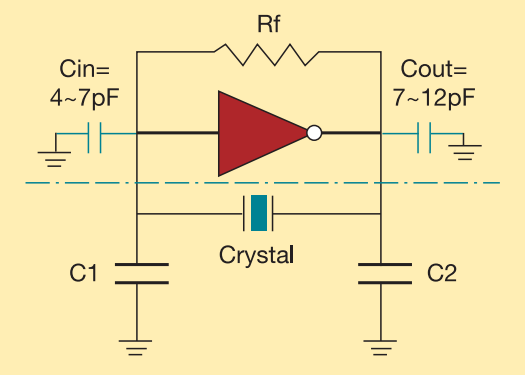
The crystal used in the topology of Figure 1 can be either a fundamental AT-CUT or BT-CUT. A BT-CUT crystal has poor frequency stability over temperature compared to an AT-CUT. This topology uses a parallel crystal and not a...
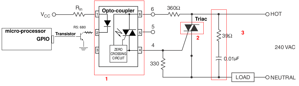
A light-dimming control system is being developed for a 240V heat lamp with a power dissipation of approximately 250W. The objective is to adjust the heat output of the lamp using control from a microprocessor. The development is based...
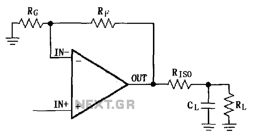
The MAX4223 to MAX4228 series incorporates a capacitive load drive circuit with an isolation resistor (RISO). The maximum allowable capacitive load for these devices is 25pF. However, exceeding this limit can lead to overshoot and ringing. The circuit design...
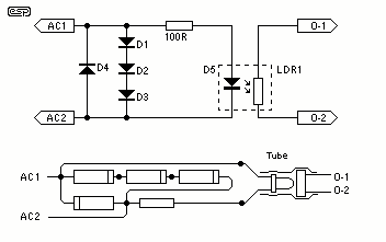
The circuit of the mains current detector is shown in Figure 1. By using a few cheap diodes, a resistor, LED and LDR, a simple opto-isolated detector can be created. This entire circuit dissipates very low power, and can...
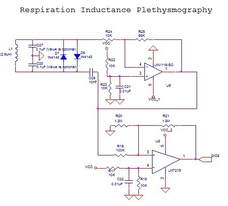
The LMV116 is an enhanced slew rate version of the LMH6645. The high-speed LMH devices are very sensitive to output capacitance (typically designed to drive back-terminated loads) and can begin to oscillate with direct capacitive loads as low as...
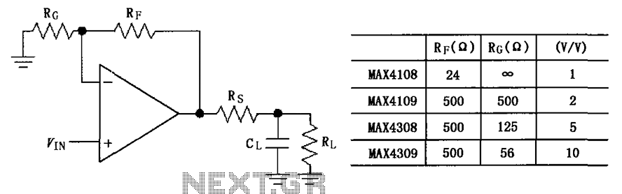
The circuit depicted in the figure employs the MAX4108/4109/4308/4309 operational amplifiers with a capacitive load driving circuit isolation resistor (Rs). While the MAX4108/4109/4308/4309 exhibits excellent AC characteristics, it is not optimized for driving high-load electrical resistances. A significant reactive...