Photoelectric isolation circuit between TTL circuit and relay circuit
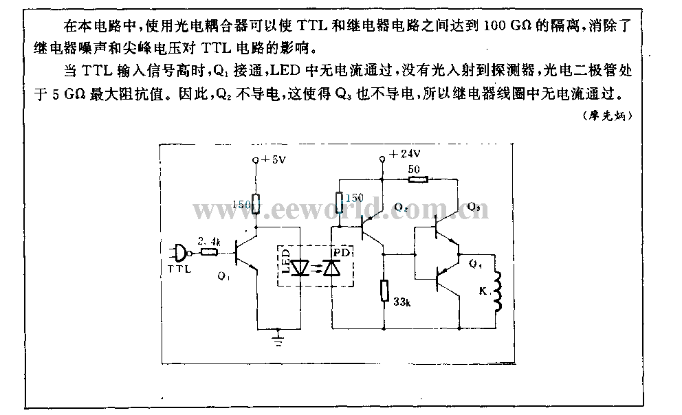
This circuit utilizes a photoelectric coupler to achieve 100GΩ isolation between a TTL (Transistor-Transistor Logic) circuit and a relay circuit. This configuration effectively prevents relay noise and peak voltage from affecting the TTL circuit. When the TTL input signal is high, transistor Q1 is activated, resulting in no current flowing through the LED. Consequently, no light is incident on the detector, and the photoelectric diode exhibits a maximum impedance value of 5GΩ. Therefore, transistor Q2 remains in a non-conducting state.
The circuit design incorporates a photoelectric coupler, which is a vital component for ensuring electrical isolation between the TTL logic circuit and the relay circuit, providing a high resistance to prevent unwanted interference. The photoelectric coupler consists of an LED and a photodetector, where the LED is driven by the TTL signal.
When the TTL signal is high, Q1 is turned on, allowing current to flow through the LED. However, in this specific configuration, it is indicated that the LED does not conduct, thus maintaining the photodetector in a state of maximum impedance. This results in Q2 remaining off, which prevents any relay activation and isolates the TTL circuit from the relay's electrical characteristics.
The 100GΩ isolation rating is critical for applications where sensitive TTL circuits must be protected from high-voltage transients and noise generated by relay operations. This isolation is achieved through the inherent properties of the photoelectric coupler, which allows signals to pass while blocking direct electrical connections.
The circuit may also include additional components such as resistors to limit the current through the LED and to ensure proper biasing of the transistors. The design should account for the specifications of the photoelectric coupler and the transistors used to ensure optimal performance and reliability. Overall, this circuit exemplifies a robust design approach for integrating TTL logic with relay control while maintaining signal integrity and protecting sensitive components from electrical noise.In this circuit, using a photoelectric coupler can reach 100G? isolation between TTL and relay circuit, it avoids relay noise and peak voltage influencing TTL circuit. When the TTL input singal is high, Q1 turns on, there is no current in LED, and there is no light incident on detecor, photoelectric diode is in 5G?
maximum impedance value. So Q2 is nonc.. 🔗 External reference
