
OpAmp based Voltage Translator Ciruit for ADC of Micro-controller
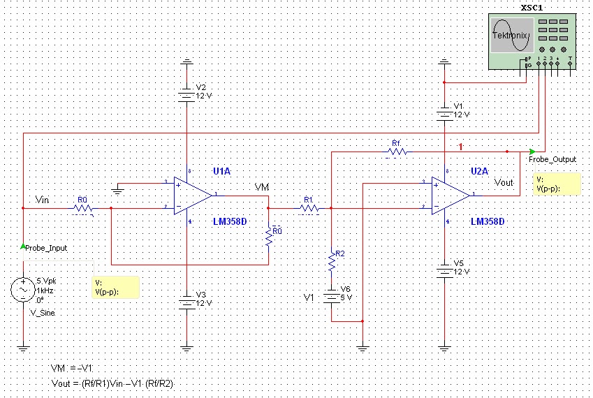
The circuit for analog signal conditioning typically consists of several key components: operational amplifiers (op-amps), resistors, and capacitors. The op-amps are configured to perform tasks such as level shifting, amplification, and filtering. A common configuration for this purpose is the inverting or non-inverting amplifier setup, which allows for the adjustment of gain to ensure that the output voltage fits within the desired range.
To achieve the necessary level shifting for a signal that ranges from -5V to +5V, a biasing method is often employed. This involves adding a reference voltage (usually 2.5V) to the input signal, effectively shifting the entire waveform upward. This can be accomplished using a voltage divider network composed of resistors that provides the required reference voltage.
Filtering is also an important aspect of analog signal conditioning. Capacitors can be used in conjunction with resistors to create low-pass or high-pass filters, depending on the application. For instance, a low-pass filter can help remove high-frequency noise from the signal, ensuring that only the desired frequency components reach the ADC.
The final output signal, which now varies from 0V to 5V, can be directly interfaced with the microcontroller's ADC input. It is crucial to ensure that the output impedance of the conditioning circuit is compatible with the input impedance of the ADC to prevent signal distortion. Additionally, proper power supply decoupling techniques should be implemented to minimize noise and ensure stable operation of the circuit.
In summary, the described circuit effectively conditions and scales analog signals from transducers, allowing microcontrollers with built-in ADCs to accurately read and process these signals while maintaining operational integrity and preventing damage.All the naturally occurring phenomena like sound, temperature and pressure etc, are analog in nature. Therefore to make an micro-controller read analog signal for analog-to-digital conversion process, through built-in analog-to-digital converter (ADC), it is necessary to subject the analog signal, generated by a transducer, to some analog signal con
ditioning and analog signal processing using analog circuits. The micro-controller can read such a signal, generated by a transducer, only if it has been conditioned and scaled down to a range which micro-controller can read for analog-to-digital conversion. This is necessary in particular for micro-controllers like AVR, PIC and Free-scale which have built-in ADCs.
These micro-controllers usually operate with 5Volts power supply. The circuits shown in the Figure1 below is appropriate for scaling down the transducer generated voltages to 0-5 Volts range. This circuit can translate the voltage falling in some other voltage range ( like -5 to +5 Volts or -10 to +10 Volts etc.
) to 0-5Volt range so that a micro- controller, being operated from 5Volt power supply, may read this signal, through its ADC input, without getting damaged. A sinusoidal input voltage of frequency 1KHz and -5V-to-+5V peak-to-peak voltage has been applied to the input of this circuit, which is translated to a sinusoidal output voltage with peak-to-peak amplitude varying from 0-5 Volts.
🔗 External reference
Related Circuits
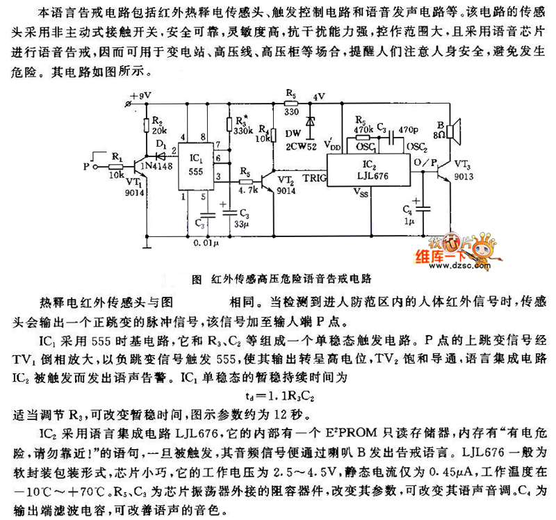
The pyroelectric infrared sensor head operates as illustrated in the accompanying figure. Upon detecting an infrared signal from a human body within its monitoring zone, the sensor head generates a positive pulse signal. This signal is transmitted to the...
The Maya utilized several calendars concurrently, one of which is known as the "long count." This calendar is a continuous record of days starting from a zero date that corresponds to August 13, 3114 BC. According to the Maya...
An internally compensated operational amplifier has been fabricated using n-channel Al-gate MOS technology, utilizing only enhancement mode devices. The circuit is designed to ensure that its performance remains insensitive to process parameters. The input stage consists of a source-coupled...
This Arduino sketch is designed to recover ATtiny microcontrollers that have become non-functional due to incorrect fuse settings. It achieves this by placing the affected ATtiny into high-voltage serial programming mode and rewriting the fuses to safe values. The...
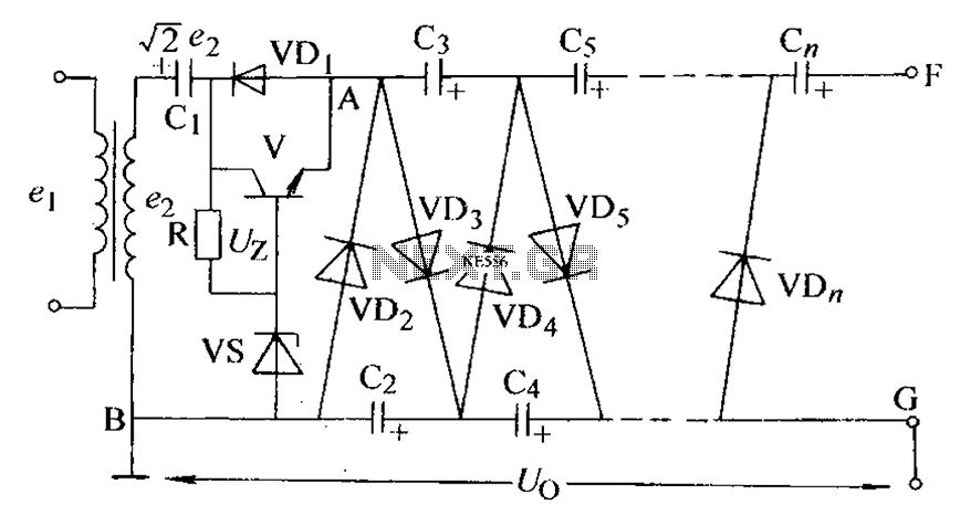
The circuit is an adjustable output voltage regulator type rectifier. It allows for obtaining peak voltage at odd multiples when the output voltage is taken from the circuit feedback (FB). Additionally, the lower point of the capacitor (CB) can...
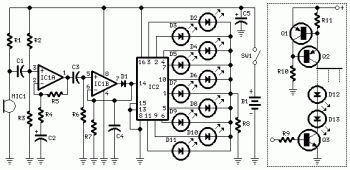
The following circuit illustrates a Dancing LEDs electronic circuit diagram. This circuit is based on the LM358 integrated circuit. Features: IC1A amplifies the signal. The Dancing LEDs circuit utilizes the LM358 operational amplifier to create a visually appealing light display....