
Infrared sensor high voltage dangerous voice warning circuit diagram
The pyroelectric infrared sensor head is designed to detect infrared radiation emitted by human bodies, making it suitable for applications such as motion detection, security systems, and automatic lighting. The sensor head typically consists of a pyroelectric element that generates a voltage when exposed to varying infrared radiation levels. This voltage change, when a human body enters the detection zone, is converted into a positive pulse signal.
The 555 timer IC, configured in a monostable mode, is an essential component of this circuit. In this configuration, the output remains low until a triggering event occurs, which in this case is the positive pulse signal from the sensor head. The resistor R3 and capacitor C2 determine the duration of the output pulse. When the signal at point P is received, the 555 timer generates a single output pulse whose width is defined by the time constant of R3 and C2. This output can be used to trigger additional circuits or systems, such as alarms or lights, enhancing the functionality of the sensor system.
The amplification of the pulse signal ensures that it is strong enough to drive subsequent components in the circuit. The design of this sensor system is critical for ensuring reliable operation in various environments, and careful selection of components such as R3 and C2 is necessary to tailor the response time and sensitivity of the system to meet specific application requirements.Pyroelectric infrared sensor head is same with the figure. When it detects the human body infrared signal in guarding zone, the sensor head will output a positive jump pulse signal, this signal is added to input terminal P point. IC1 adopts 555 time base circuit, the monostable trigger circuit is composed of 555 and R3, C2. P`s jump signal is phased and amp.. 🔗 External reference
Related Circuits
The preamp featured has optional tone and balance controls which may be omitted if desired. The input switching may be extended if needed to accommodate more signal sources. In this version, no RIAA (phono) input is provided. See the...
Take care with transmitter circuits. It is illegal in most countries to operate radio transmitters without a license. Although only low power this circuit may be tuned to operate over the range 87-108MHz with a range of 20 or...
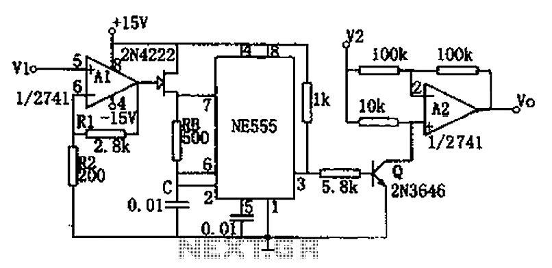
The circuit depicted in the figure consists of a voltage-frequency converter and an amplitude modulator. The input voltage V1, processed by operational amplifier A1, controls the FET 2N4222's internal resistance, which in turn alters the oscillation frequency of the...

This design circuit for audio amplifiers with DC coupling to the load is not commonly used today, despite its clear advantages. One advantage is the elimination of the need for a second (symmetric) power supply, and another is the...
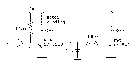
To control a stepper motor, each winding must be energized individually in a specific and timed sequence. This energization is carried out by a driver circuit, which acts as an amplifier. The timing is managed by an indexer circuit,...
The circuit consists of two main components: (1) a power supply circuit featuring a transformer (T) that steps down AC 220V to 33V, followed by a full-wave rectifier, a filter, and a three-terminal regulator that outputs +24V. This circuit...