
opt301 laser receiver

The OPT301 circuit design is optimized for applications requiring high sensitivity in the infrared and visible light spectrum, making it suitable for various photodetection tasks. The choice of a TO-99 package not only contributes to its compactness but also enhances thermal stability and mechanical robustness. The use of a single supply voltage simplifies the power management aspect of the design, while the high-value feedback resistor ensures that the detector maintains its sensitivity across the specified wavelengths.
The implementation of the NE5534 op-amps is critical in achieving low noise and high fidelity in signal processing. The first NE5534 configured as a bandpass filter is essential for isolating the desired frequency components from unwanted noise, providing a clear signal for further amplification. The subsequent inverting buffer amplifier increases the signal strength without introducing significant distortion, which is crucial for maintaining the integrity of the received signals.
The mechanical design considerations, such as mounting the detector in a metal enclosure and ensuring proper isolation from the ground plane, are vital for minimizing electromagnetic interference and ensuring consistent performance. The countersunk holes for the TO-99 package facilitate secure mounting and thermal management.
Overall, the OPT301 circuit is tailored for precision applications in photodetection, especially for systems utilizing low-level signals in the presence of noise, making it a valuable component in modern electronic communication and signal processing systems.The OPT301 is in a TO-99 8 lead package and has good sensitivity but a reduced bandwidth of 4kHz. The peak response is just into the Infra Red region at 750nm but its sensitivity in the visible red spectrum at 670nm is only a few percent down. The circuit is almost identical to the original receiver. Changes are the new detector / PCB layout and i mproved op-amps. It uses a single supply at 12 - 13. 8V. The detector has a a 10M Ohm feedback resistor soldered directly betw1een pins 2 and 5. The detector output is followed by a NE5534 low noise op-amp (3. 4nV/Hz) which is configured as a bandpass filter. The final NE5534 is an inverting buffer amplifier with a gain of 20. The complete detector assembly is designed to be mounted in a small metal box at the focal point of a lens. The track is viewed from the top or component side. The detector is fitted to the other side of the board where a groundplane in unetched copper has holes countersunk for the TO-99 package.
With a single supply line the body of the detector is held at the zener voltage. Therefore it should be isolated from the groundplane and from any metal enclosure. To evaluate the op-amp section I connected a 600 Ohm sig gen to the input of the bandpass filter and measured the response at the output of the buffer. The Input was adjusted from 50Hz to 3kHz with a constant level of 200mV Peak to Peak. As you can see from the results below, the 6dB bandwidth is just 200Hz. This makes the detector ideal for transmitters using modulated CW on a fixed frequency. My TX uses a 4MHz crystal and a CMOS 4060 oscillator / divider to generate 488Hz. This degree of accuracy gives the option of using a lap top and modern DSP softw1are (e. g. ARGO or Spectran by IK2PHD) to receive signals 20dB below normal noise level. 🔗 External reference
Related Circuits
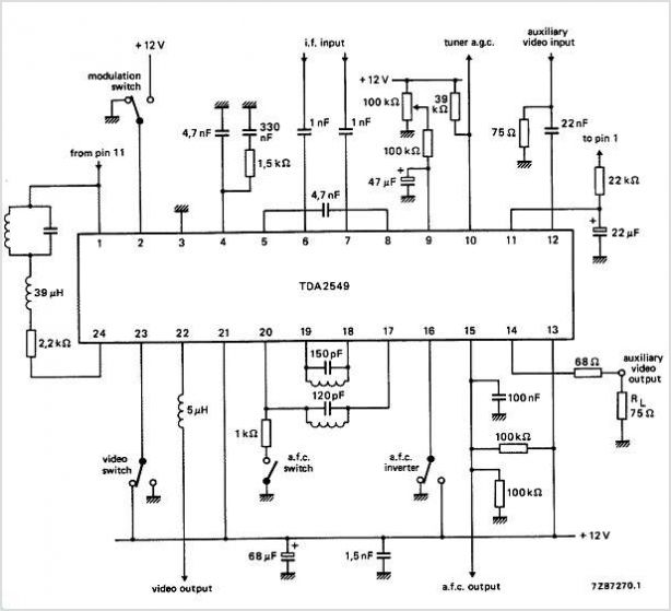
The circuits utilize two FM Demodulator TDA2555 systems to execute the demodulation functions necessary in a dual sound carrier television system for demodulating the sound carriers. The distinction between the TDA2555 and TDA2557 lies in the number of stages...
This is a compact three transistor regenerative general coverage receiver with fixed feedback. It's based on the principle of the ZN414 only much higher coverage. The sensitivity and selectivity is relatively good (especially on the LF and MW bands)...
Free-space optical (FSO) communication utilizes light as a medium for data transmission. Communication was established between two computers using a laser, independent of any conventional communication methods. Text messages were sent from one PC to another using a system...

This circuit is designed for precise centigrade temperature measurement. It features a transmitter section that converts the sensor's output voltage, which is proportional to the measured temperature, into frequency. The output frequency bursts are transmitted through the mains supply...
The Passive Aircraft Receiver is an amplified "crystal radio" intended for receiving nearby AM aircraft transmissions. Its "passive" design does not incorporate oscillators or other RF circuitry that could interfere with aircraft communications, making it suitable for use within...
This train detector makes use of hand held laser pointer devices that are widely available to detect trains over long distances. The described train detector system utilizes handheld laser pointer devices as a primary component for the detection of trains...