Laser Pointer Train Detector
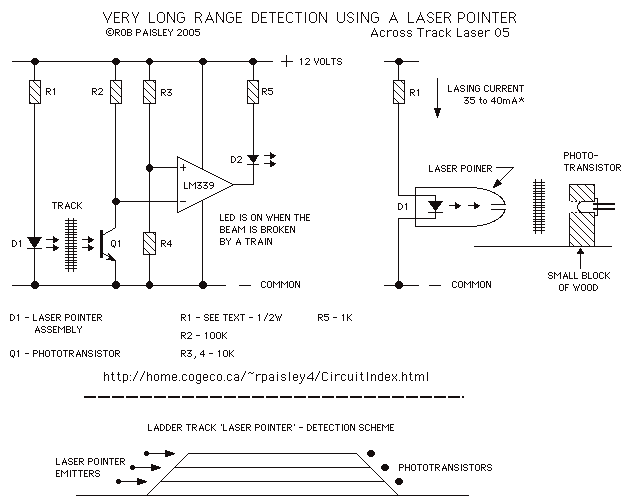
This train detector makes use of hand held laser pointer devices that are widely available to detect trains over long distances.
The described train detector system utilizes handheld laser pointer devices as a primary component for the detection of trains over extended distances. The operation of this system hinges on the principles of laser beam projection and reflection. The laser pointer emits a coherent beam of light that can travel significant distances with minimal dispersion.
To implement this system effectively, a receiver must be positioned at a predetermined location along the train's route. This receiver can be a photodiode or a phototransistor, which is sensitive to the wavelength of the laser light emitted by the handheld device. When the train approaches, it interrupts the laser beam, causing a change in the light intensity detected by the receiver.
The output from the photodiode can be fed into a microcontroller or a comparator circuit, which will process the signal. If the beam is interrupted, the circuit can trigger an alert system, such as an LED indicator or an audible alarm, to notify personnel of the approaching train. The circuit may also include a delay timer to prevent false alarms caused by transient interruptions, such as small animals or debris.
Power supply considerations for both the laser pointer and the detection circuit must be addressed. The laser pointer typically operates on standard batteries, while the detection circuit may require a stable voltage source, which could be achieved using a voltage regulator if the supply voltage is variable.
In summary, this train detection system is an innovative approach that leverages readily available laser technology to enhance safety and monitoring capabilities along railway lines. Its design can be adapted for various applications, including remote monitoring and integration with existing railway signaling systems.This train detector makes use of hand held laser pointer devices that are widely available to detect trains over long distances. 🔗 External reference
