
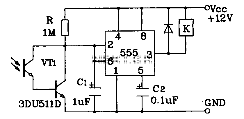
Optical switch detector with 555
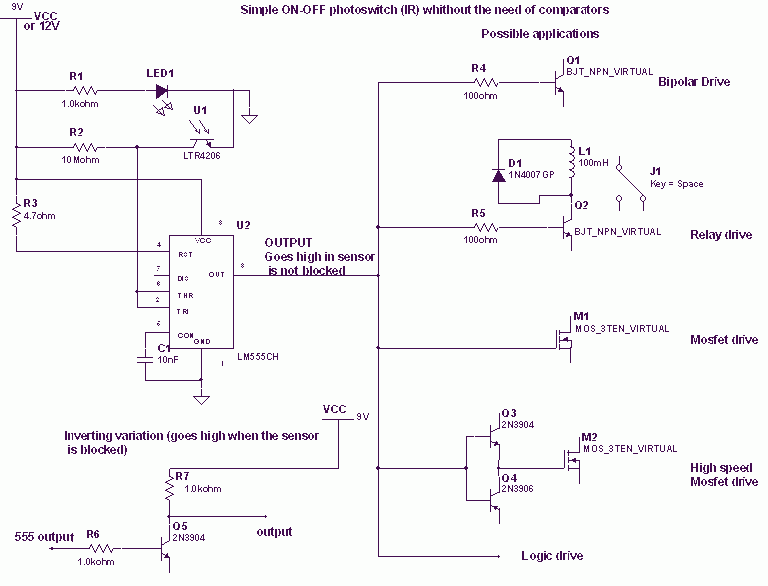
The circuit described involves a phototransistor used as a light sensor, which operates in conjunction with a 555 timer IC configured in a monostable or astable mode depending on the application. The phototransistor's operation is based on the principle that it conducts current when exposed to infrared (IR) light, leading to a voltage drop across a resistor connected to its collector. This voltage drop is crucial for triggering the 555 timer.
The 1 MΩ resistor plays a pivotal role in setting the threshold voltage at which the 555 timer activates. The relationship between the collector current (Icollector) and the resistor value (R) determines how much light is needed to bring the voltage at the collector down to the threshold of VCC/3. By adjusting the resistor value, the sensitivity of the phototransistor can be modified, allowing for the detection of varying light levels. For high-sensitivity phototransistors, a lower resistance is required, while weaker phototransistors necessitate higher resistance values. The inclusion of a trimmer resistor allows for fine-tuning of the sensitivity, providing flexibility in different lighting conditions.
The 555 timer IC, known for its robustness, can drive a variety of output devices, including relays and MOSFETs, making it suitable for applications such as alarms or switching mechanisms. In scenarios where an action is required upon the interruption of light (e.g., a burglar alarm), the output of the 555 timer may need to be inverted. This inversion can be achieved using a small bipolar transistor arranged in an inverting configuration. Alternatively, the configuration can be modified by repositioning the phototransistor and resistor, ensuring that the voltage at the collector drops below VCC/3 when the light is blocked.
Overall, the described circuit provides a versatile and effective means of detecting IR light and triggering various outputs based on the light's presence or absence, suitable for numerous electronic applications.When the phototransistor is stroken by IR light it conducts and the voltage between the 1Mohm resistor(arbitrary) and the phototrans drops from VCC to lower values. When the voltage drops lower than VCC/3 the 555 is triggered and goes high (from 0 TO VCC). The amount of light that strike the phototrans necessary to bring his collector to VCC/3 is determined by the resistor (Vdrop = Icollector * R , so , if Vdrop= 2*VCC/3, the resistance needed to set the threshold on current is R=2*VCC/(Icollector*3)).
High sensibility phototrans would need a smaller resistor, and weaker phototransistors higher value resistor, you can also use a trimmer to set the on threshold level with precision. The time of phototransistor isn't critical. The 555 has high current capability and can drive various devices, such as Bipolars, relays, bipolars+relays, mosfets, mosfets + totem pole , or give a logic output.
In case you need to trigger something when the gate is blocked (for example a burglar alarm, or a multistage coilgun) you need to invert the output, which is accomplished using a small bipolar transistor wired in an inverting setup (see pic) or swapping the positions of phototransistor with the resistor, so the voltage will drop under VCC/3 when blocked: The formula to determine the resistance to turn off at Icollector is R=VCC/(Icollector*3). 🔗 External reference
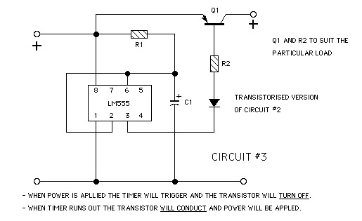
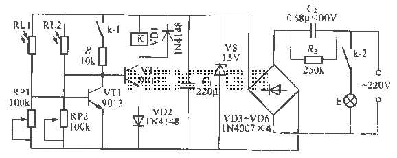
Related Circuits
The digital thermometer consists of a temperature sensor, a single stabilizing circuit, a counter circuit, a decoding section, a driving circuit, and LED digital tubes among other components. It operates within a temperature range of 0 to 50 degrees...
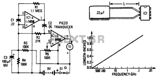
A simple radar signal detector utilizes the junctions of the input transistors of an LM1458 operational amplifier as RF detectors. The leads of the integrated circuit function as an antenna and should be approximately 0.4 inches long, measured from...
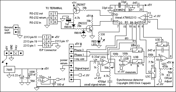
This circuit utilizes a synchronous demodulator to extract a 1 kHz signal from noise and measures its amplitude, with the 1 kHz signal providing a resolution of approximately 60 microvolts per count. The measurements are transmitted via an RS-232...
Darlington phototransistor type light-sensitive switch control circuit application. The Darlington type phototransistor serves as a sensitive element, capable of detecting low light levels for the detection of reflected light signals. The Darlington phototransistor circuit utilizes a pair of transistors configured...
The goal is to create a small light that is activated by motion and stays illuminated for 20 seconds before turning off. For example, when the light is picked up, it illuminates, and when placed back down, it remains...
This is a remote-controlled light switch circuit that can be used for remote control toys, flashlight operation, or laser pointers. When the light from a torch illuminates the photosensitive resistor RL2, its resistance decreases, causing transistor VT2 to turn...