
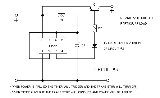
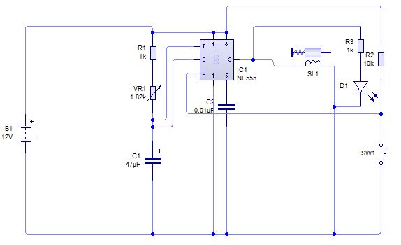
555 timer motion led circuit
To construct the motion-activated light circuit, a few key components will be necessary. The primary components include a motion sensor, a microcontroller or timer, a relay or transistor for switching the LEDs, and the LEDs themselves.
1. **Motion Sensor**: A passive infrared (PIR) sensor can be employed to detect motion. When motion is detected, the sensor will send a signal to the microcontroller or timer to activate the light.
2. **Microcontroller/Timer**: A simple microcontroller, such as an Arduino or a timer IC like the NE555, can be programmed to turn on the LEDs when it receives a signal from the motion sensor. The microcontroller can be set to keep the LEDs illuminated for 20 seconds before turning them off automatically.
3. **Relay/Transistor**: To handle the current required by the LEDs, a relay or a transistor can be used. This component will act as a switch, allowing the microcontroller to control the power supplied to the LEDs without exceeding its current rating.
4. **LEDs**: The 10 LEDs will be connected in parallel or series, depending on the desired voltage and current specifications. It is important to ensure that each LED has an appropriate current-limiting resistor calculated based on the supply voltage and the forward voltage of the LEDs.
5. **Power Supply**: A battery holder will be used to supply power to the circuit, ensuring that the voltage matches the requirements of the LEDs and other components.
6. **Capacitors**: Capacitors may be required for smoothing out voltage fluctuations and ensuring stable operation of the microcontroller or timer.
7. **Resistors**: The 510-ohm resistors can be used for current limiting for the LEDs. The calculation for the resistor is indeed correct: Rseries = (Vpower - Vf) / I, where Vpower is the supply voltage, Vf is the forward voltage of the LED, and I is the current drawn in milliamps.
The assembly will take place on the stripboard, where each component will be soldered in place according to the schematic. The design should ensure that all components are securely mounted and that the connections are reliable to prevent any failures during operation. Finally, the entire assembly will be enclosed within the translucent acrylic box, allowing the light to shine through while protecting the electronics from external damage.The objective is to make a small light that is activated by motion and will remain on for 20 seconds and then deactivate. i. e. you pick up the light it illuminates youput it back down and it remains on for 20 seconds then turns itself off.
until it is picked up again. I have a load of 510ohm 1/4w resistors(came free with tthe LEDs) but can easily buy more once I know what is needed. I dont have any capacitors but guess I`ll need some of those also, what size I dont know where to begin. Anything else I might need Could someone help me out in getting these components onto a circuit to do the above task.
If possible explaining it in layman terms so a simpleton like myself can purchase any extra parts and solder it all together. All electronics will be concealed inside the device which is being made out of 3mm translucent acrylic, Ive tested and 10 LEDs is suffient to illuminate through this.
The batteries will be held in a battery holder(similar to this ) on the underside of the light box. I have some stripboard to mount the circuit. Im not sure if I have any more than I have already provided. they look exactly like the normal 5mm two legged ones. only difference is they change colour slowly. All electronics will be concealed inside the device which is being made out of 3mm translucent acrylic, Ive tested and 10 LEDs is suffient to illuminate through this. The batteries will be held in a battery holder(similar to this ) on the underside of the light box. I have some stripboard to mount the circuit. Im not sure if I have any more than I have already provided. they look exactly like the normal 5mm two legged ones. only difference is they change colour slowly. A big thanks for helping with this, electronics are like a foreign language for me. The light box is to be a part of a presentation, intially I was just going to dismantle an LED torch and use the gubbings from that but then decided it would be better if I attempted the circuit myself and had it do what I wanted.
Having no knowledge of electronics I bite off more than I can chew, Im willing to learn so your help is very much appreciated. With regards to the math, am I correct in thinking that Rseries is the calculation for the resistor required = (power voltage - forward voltage) divided by the mA drawn.
By your calculation this is 180R. Is R equal to ohms 🔗 External reference
Related Circuits
A small comparator (MAX9060/MAX9061 or MAX9028) safeguards the LED driver in a backlit display when the LEDs are disconnected, by producing a shutdown signal that eliminates the LED voltage. The MAX9060/MAX9061 and MAX9028 are high-speed voltage comparators designed for applications...
The TDA integrated circuit series is highly regarded and widely utilized in amplifier designs and projects. TDA audio amplifier circuits are primarily produced by Philips and SGS-THOMSON. The most commonly used ICs include the TDA2030 and TDA2003 for small...
The voice recorder's entry information can be stored for 100 years, repeated 100,000 times, with low power consumption. It requires a 5-6V DC power supply and has a recording current of 2 mA. The voice recorder circuit is designed to...
A circuit is being designed to trigger solenoid valves for airbags in a car, requiring a time range of 0 to 1 second. The selected valves operate at 12V, 0.5A, and can activate within a maximum speed of 200...
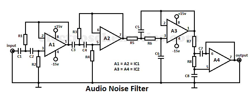
This audio noise filter circuit is a bandpass filter designed for the audio frequency range. It effectively filters out unwanted signals that fall below or above the audio frequency spectrum. The audio noise filter circuit operates as a bandpass filter,...
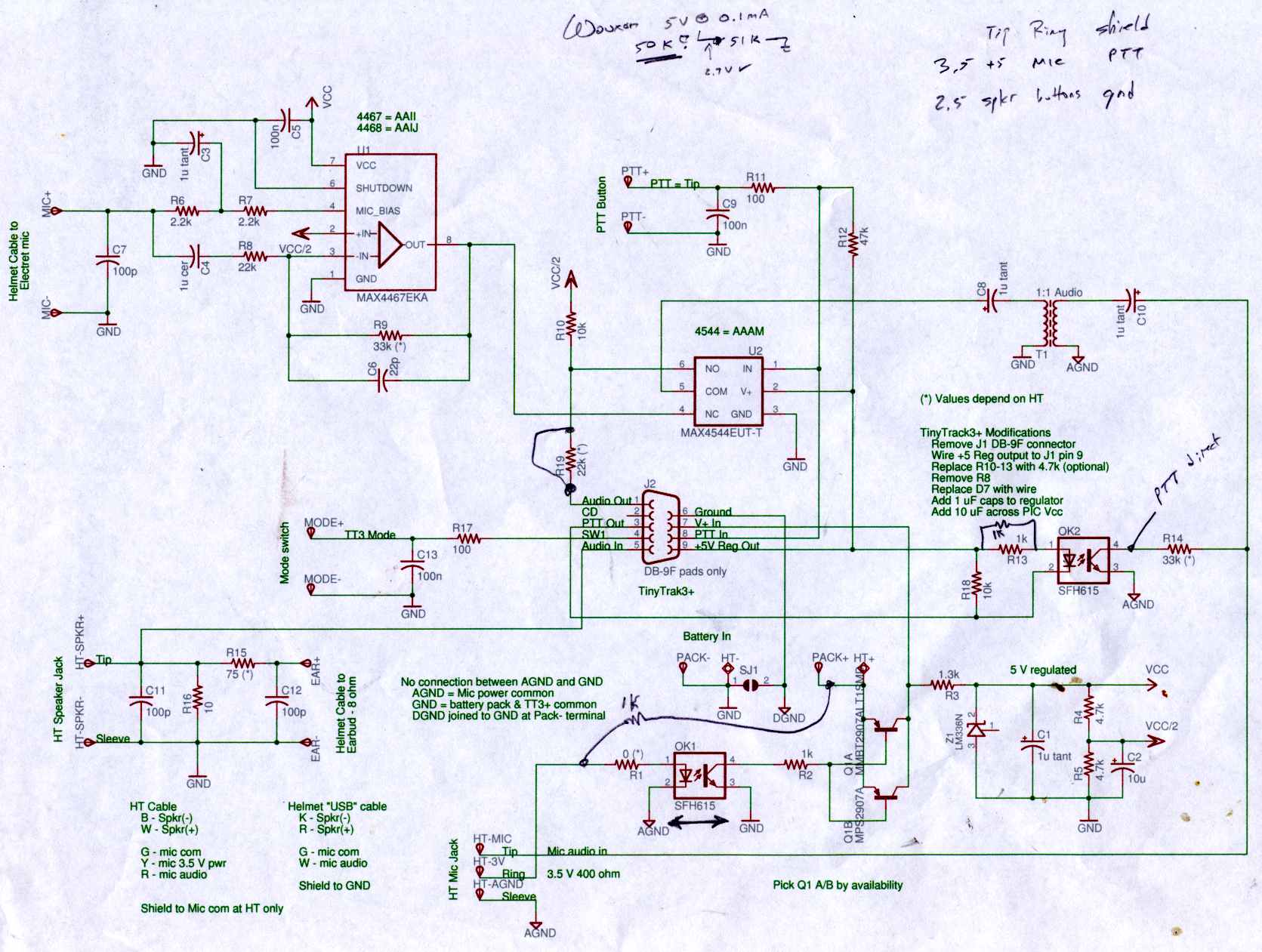
Connect the Byonics TinyTrak 3+ GPS modem, helmet earbud/mic, and external battery pack to the Z-1A, which is incompatible with the Wouxun. The KG-UV3D utilizes the Kenwood HT interface with a single ground for mic, speaker, and PTT functions,...
Warning: include(partials/cookie-banner.php): Failed to open stream: Permission denied in /var/www/html/nextgr/view-circuit.php on line 713
Warning: include(): Failed opening 'partials/cookie-banner.php' for inclusion (include_path='.:/usr/share/php') in /var/www/html/nextgr/view-circuit.php on line 713