
One KHz Synchronous Detector Circuit
This circuit design is particularly effective in environments with significant noise, allowing for precise measurement of small signals. The use of a synchronous demodulator enhances the ability to distinguish the desired signal from background noise, making it suitable for applications in various fields, including telecommunications, scientific research, and industrial monitoring. The integration of the AT90S2313 microcontroller allows for efficient processing and data handling, ensuring that the system operates seamlessly while maintaining high sensitivity and accuracy.This circuit employs a synchronous demodulator to separate a 1 KHz signal from noise and measures the amplitude with the 1 kHz signals when a 2nd at about 60 microvolts per count then sends the measurements via an RS-232 interface for further processing or exhibit. An LED about the board also lights when the measured signal exceeds a preset thresh old. This experiment was began when I took an interest in getting ELF wireless signals. It also has applictions in optics and superior frequency RF, or for that matter, any place one wants to measure a small signal, of which the frequency and phase are recognized, in the presence of noise. Using the addition of the preamplifier according to the LM324, the sensitivity of this circuit was very easily extended to a sensitivity to 160 nanovolts per count.
That an LM324 is utilized with little within the way of noise about the output testifies to the worth of employing this type of detector. The incoming signal is buffered by U2A (there is on U1 with this schematic as U1 was moved to a separate preamp assembly), which delivers a noniverted signal towards the integrator when U3A is switched on.
U2B inverts the buffered signal from U2A and offers an inverted edition of the signal towards the integrator when U3B is switched on. To increase the charging fee, possibly reduce the 100k resistor around the input of U2C or decrease the.
047 uf integrating capacitor. The signals fed into the integrator charge the. 047 uf capacitor within the integrator. Right after 999 cycles with the 1 kHz sampling signal, U3C is turned on plus the capacitor is discharged with a continual current (one. 8V/7. 5K = 240 microamps), creating a linear positive-going ramp at five, 106 volts/second on the output of U2C.
Though the output of U2 is ramping up toward the one. eight volt reference, the AT90S2313 sits inside a loop, incrementing a counter each and every 1. 25 microseconds, until the comparitor around the AT90S2313 modifications state, indicating that the ramp on U2C has reached the one. 8 volt reference voltage. The optimum count for this measurement is 127 to restrict the time invested in the measurement to less than the 250 microsecond interrupt interval.
Therefore, a 7 bit measurement is created in 160 microseconds or much less, and it is finished within a single 250 microsecond interrupt interval. The charge of discharge in the integrating capacitor throughout the measurement phase is set through the present in to the node, 1.
eight volts/7. five k =240 microamps, divided by the. 047 uf capacitance, which offers a 5100 volt/second voltage ramp. The A/D conversion sensitivity is therefore 1. 25 us/count X 5100 volts/second = 6. 375 millivolts per count. Immediately after the count is completed, which happens when the pseudo 7 bit counter overflows or even the ramp reaches the 1. 8 volt reference, U3C is switched off and U3D is switched on to clamp the of your integrator to the one.
eight volt reference and to make sure the capacitor is discharged to a consistent state for one millisecond before beginning signal measurement once more, The entire measurement cycle requires 999 milliseconds for integration + one millisecond to clamp the capacitor to zero, for a total of one second per measurement. The gian in the integrator is ( ( Peak input Voltage/ a hundred k Ohm) X 0. 999 seconds ) )/. 047 microfarads = 212. 5 volts out/volt in. The sensitivity of your detector is for that reason six. 375 mv/212. 5 = thirty microvolts peak per count, or because peak-to-peak = 2 x peak, 60 microvolts peak-to-peak per count.
Immediately after the measurement is completed, the measured worth is formatted into BCD and sent through the UART at 9600 baud, two stop bits, no parity. The transmission with the data does not happen during interrupt time. An LED is turned on by the microcontroller in the course of the integration and measurement cycle following a measurement during which the measured worth exceeded 64 decimal.
🔗 External reference
Related Circuits
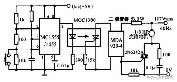
The switch shut-off time delay circuit consists of a timer, optocouplers, a bridge SCR, and an SCR AC switch. When the control button is released, it allows the motor or other AC power to remain active for one hour....
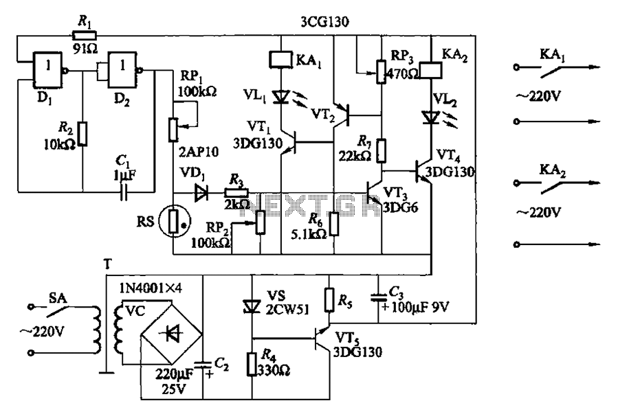
Two NAND gates (Di, Dz) and a resistor (Rz) along with capacitors (C1, etc.) form an RC self-excited multivibrator with an oscillation frequency of 2.5 Hz and an oscillation amplitude of 4 V. This circuit is used as a...
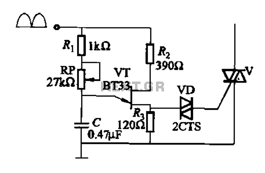
Figure 16-29 (a) illustrates the trigger output through a resistor R2, while Figure 16-29 (b) depicts the integration of a programmable unidirectional transistor (PUT) trigger circuit. The adjustable potentiometer RP can modify the conduction angle of the TRIAC to...
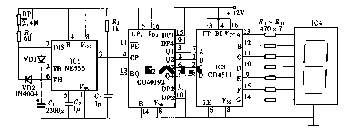
Digital timers feature a clear and precise display. They represent time intervals based on pulse signals, which are decoded by a digital device with a digital display unit. The circuit described pertains to a digital display for these timers,...
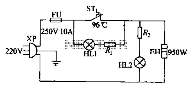
The 220V electric vibrator features a clip for insertion, with FU representing the fuse. ST indicates an inverter-like device, while HL1 and HL2 serve as indicators for insulation and heating. The EH component functions as the heater. When the...

This circuit is designed as a pocket-sized, high-performance audio oscillator. It can operate using a battery-powered version, which is feasible at a very low cost by utilizing a single quad op-amp to provide the entire active circuitry. The design...