
Optical Theremin

The optical Theremin circuit leverages the properties of light-dependent resistors to modulate sound frequencies and volume in response to hand movements. The LDRs are sensitive to changes in light intensity, which allows for a unique method of interaction compared to traditional Theremins that rely on capacitive sensing.
In the circuit, LDR1 is connected to a frequency oscillator, which generates audio signals at varying pitches based on the light intensity detected by the resistor. When a hand moves closer to the aperture, the amount of light reaching LDR1 increases, resulting in a lower resistance and consequently a higher frequency output. Conversely, moving the hand away reduces the light exposure, increasing the resistance and lowering the frequency.
LDR2 functions similarly, but instead of controlling frequency, it adjusts the amplitude of the output signal. This is achieved by varying the resistance in a voltage divider configuration, affecting the overall gain of the audio signal sent to the loudspeaker.
The design of the boxes containing the LDRs is crucial for achieving the desired responsiveness. The apertures should be designed to allow for smooth manipulation of light exposure while minimizing external light interference. It is beneficial to ensure that the boxes are enclosed to maintain stable ambient light conditions, thereby enhancing the performance of the optical Theremin.
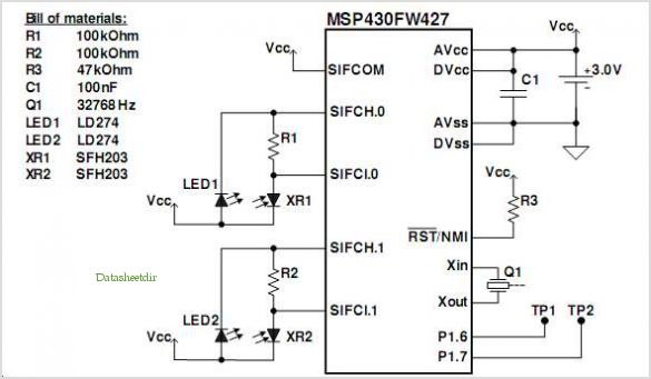
The final audio output, although initially low in volume, can be connected to an audio amplifier to achieve a more pronounced sound. The use of a standard audio power amplifier allows for flexibility in sound output levels, making the optical Theremin suitable for various applications, from experimental music to educational demonstrations in electronics and sound synthesis.Normally, Thereminworks by detecting hand proximity using capacitive coupling method. A Theremin circuit shown in the schematic diagram below use different method to control the pitch. The oscillator of this tone generator, both the volume and frequency are controlled using LDRs, a light sensitive electronic component, so we can call this circuit anoptical Theremin. Look at the following schematic diagram: LDR1 control the frequency of this Theremin, while LDR2 control the volume level. We can place the LDR in two boxes where we can use our hand to control the aperture of the box, allowing smooth control of light amount that expose the LDR.
This light is expected to come from ambient light, entering the box through the hand controlled aperture. This optical Theremin assume a stable ambient light to produce smooth control. The output will be heard on a small loudspeaker, but will be in very low volume. You can just amplify this output with a standard audio power amplifier to get better loudness. 🔗 External reference
Related Circuits
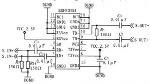
The SP1481E, SP1485E, SP1490E, and SP1491E series transceivers, combined with the SP6652 high-efficiency, high-frequency current mode PWM buck regulator, facilitate the creation of an isolated RS-485 interface capable of providing up to 2kVrms isolation. This configuration supports CAN communication...
This is a luminous flux test circuit that utilizes optical resistors. In the circuit, the optical resistor RG forms a bridge with resistors RP1, RP2, R1, and R2. RP1 is employed to balance the bridge, while RP2 is used...
An article previously discussed connecting to the Raspberry Pi board from a Linux PC using the serial port. This time, the focus is on how to achieve the same connection using a Windows PC. In this case, a Windows...
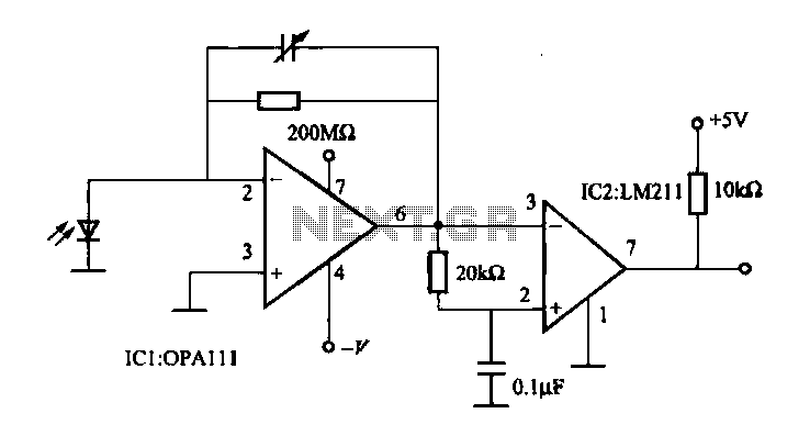
The OPA111 optical receiver amplifier features a feedback resistor of 200 MΩ, which is crucial due to the high gain of the amplifier. The OPA111 is designed to receive signals transmitted over optical fiber, specifically at a rate of...
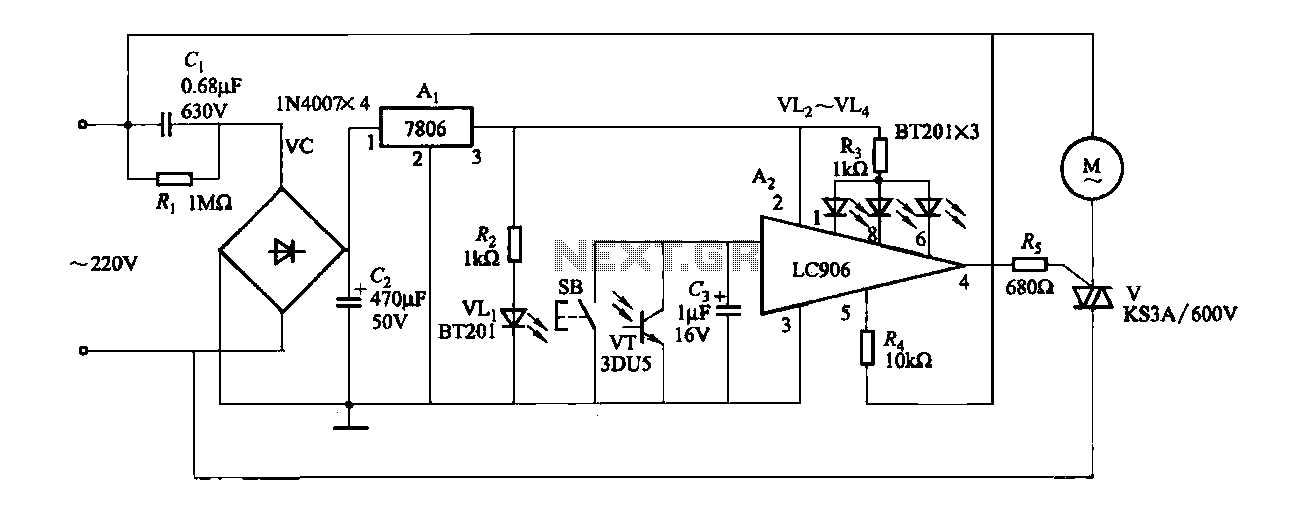
The ceiling fan speed control circuit depicted in Figure 3-6 utilizes a capacitor step-down method and a three-terminal fixed 7806 voltage regulator. It achieves fan speed control through the integrated circuit A2, which regulates the conduction angle of the...
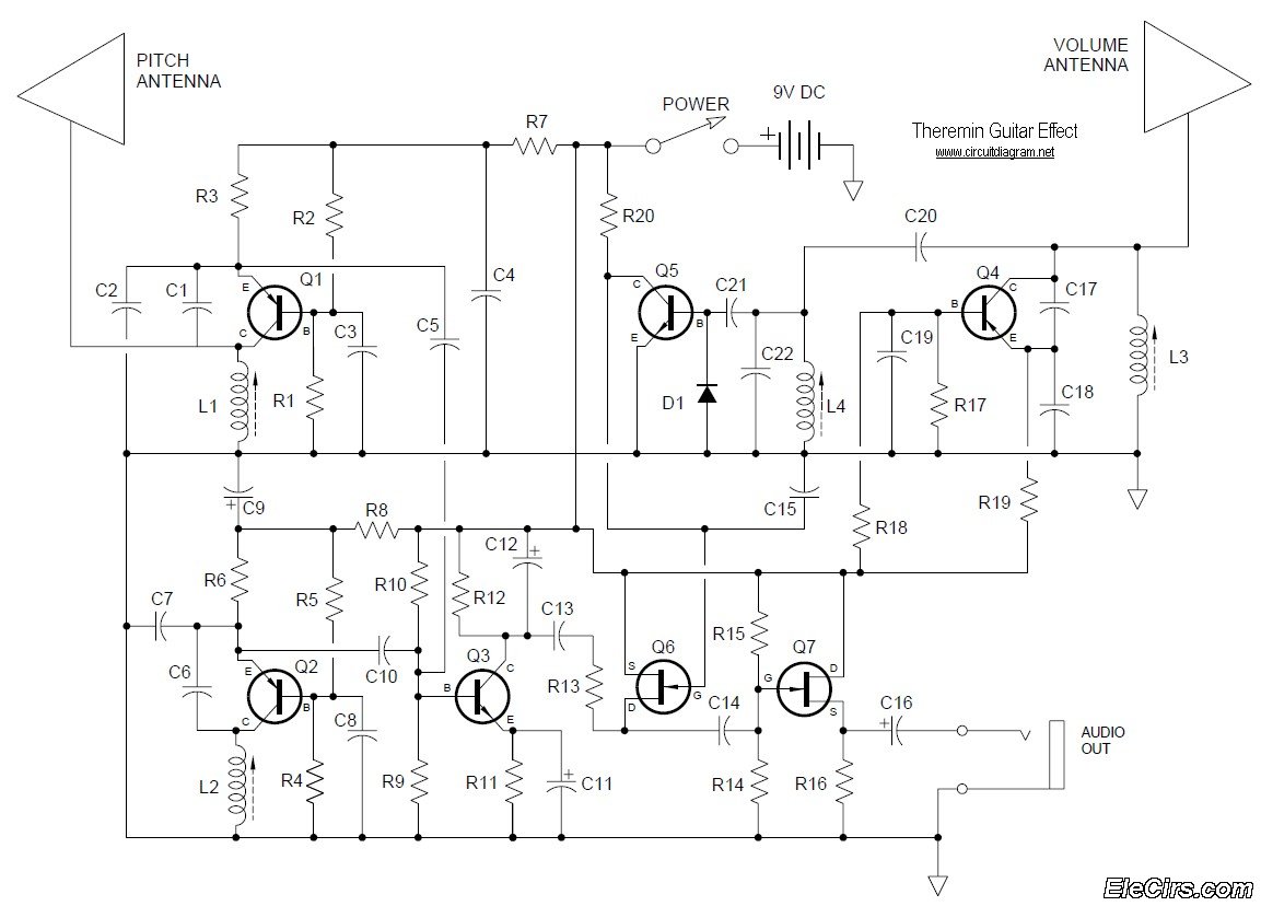
Below is the circuit diagram for the Theremin music instrument effect. A guitar or instrument amplifier is an ideal companion for the Theremin, allowing for bass or treble boost as desired, as well as fuzz (distortion) or reverberation if...