
The luminous flux test circuit with optical resistors
The luminous flux test circuit is designed to measure light intensity using a configuration of optical resistors, which change their resistance based on the amount of light exposure. The core of this circuit is a Wheatstone bridge formed by RG, RP1, RP2, R1, and R2. The optical resistor RG responds to light levels, altering the resistance and thus influencing the balance of the bridge.
Resistor RP1 serves a critical role in fine-tuning the bridge balance. By adjusting RP1, the user can achieve equal voltage levels at nodes a and c, which is essential for accurate measurements. The second variable resistor, RP2, is responsible for adjusting the sensitivity of the entire circuit, allowing the user to calibrate the response to varying light conditions.
When the circuit is balanced—meaning the voltages at points a and c are equal—the output voltages VT1 and VT2 drop to zero. This condition indicates that the thyristor in the VSI section of the circuit is no longer conducting, effectively turning it off. The design ensures that the circuit can operate effectively under different lighting conditions by providing a means to adjust both the balance and sensitivity, making it suitable for applications requiring precise luminous flux measurements.
Overall, this luminous flux test circuit exemplifies the use of optical resistors in a bridge configuration to achieve accurate light intensity readings, with adjustable parameters for fine-tuning performance.This is a luminous flux test circuit with optical resistors. In the circuit, the optical resistor RG forms a bridge with RP1,RP2,R1 and R2; RP1 is used to adjust the balance of the bridge; RP2 is used to adjust the sensitivity of the circuit. If we adjust RP1 to make the voltages on a and c are equal, then VTl and VT2 stop, and the thyristor of VSI is off.
I.. 🔗 External reference
Related Circuits
This is a circuit which I originally included in my book, 22 Tested Transistor Projects, published by Babani Press in 1976 (ISBN 0 900162 63 S). It is one I had great fun with. It uses the PUT Complimentary...
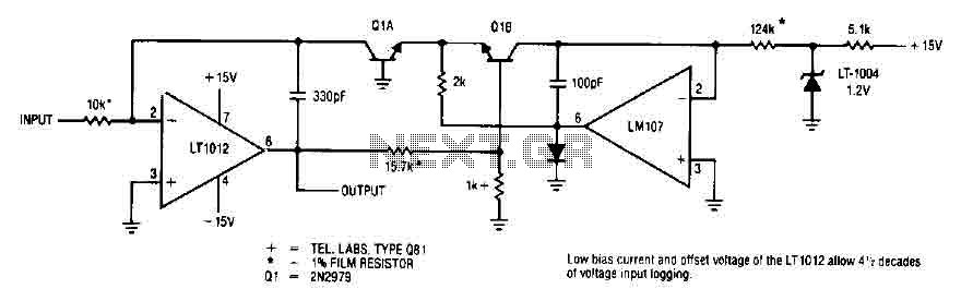
This simple logarithmic amplifier circuit uses the LT1012, which has a low bias current that allows for 4.5 decades of voltage input logging. Additionally, transistors that can be used in this circuit include the 2N2979. The logarithmic amplifier circuit designed...

The circuit diagram illustrates a digital precision pressure tester using the MAX1457 integrated circuit with an external ROM selection of the 93C66 type, which is a 4096-bit E2PROM. Upon powering on, the MCS pin is pulled to a high...
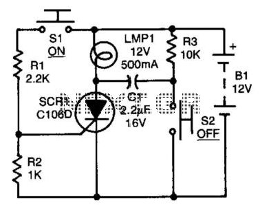
After the SCR is activated, capacitor CI charges up to nearly the full supply voltage through resistor R3 and the anode of the SCR. When switch S2 is later closed, it grounds the positive terminal of CI, causing the...
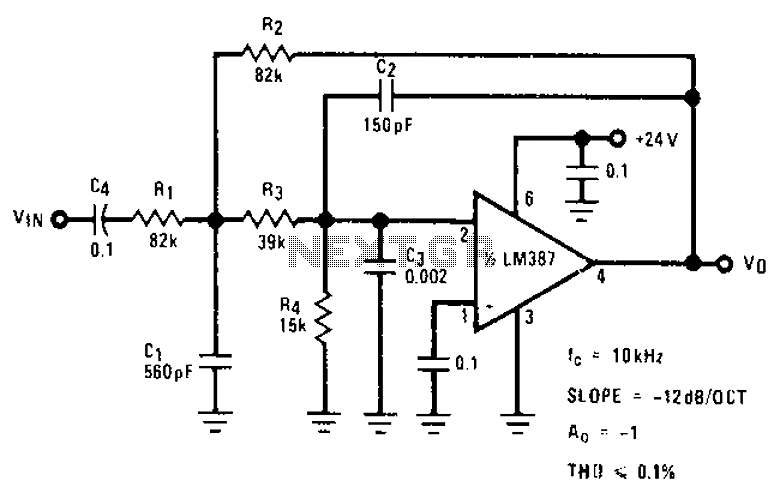
The circuit provides a passband gain of 1 with a corner frequency of 10 kHz, designed to eliminate high-frequency noise such as hiss, ticking, and popping sounds. This circuit operates as a low-pass filter, effectively attenuating frequencies above the specified...
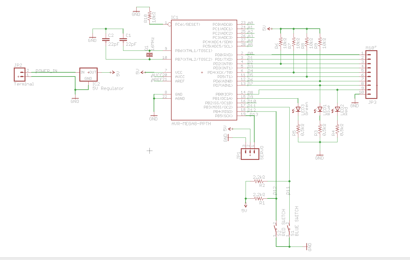
A circuit utilizes a keypad, a servo, and several LEDs, connected to an Arduino Uno. The objective was to integrate all components onto a single PCB, effectively creating a custom version of the Arduino. Upon startup, the red LED...