
Five stalls can control fan speed optical circuit
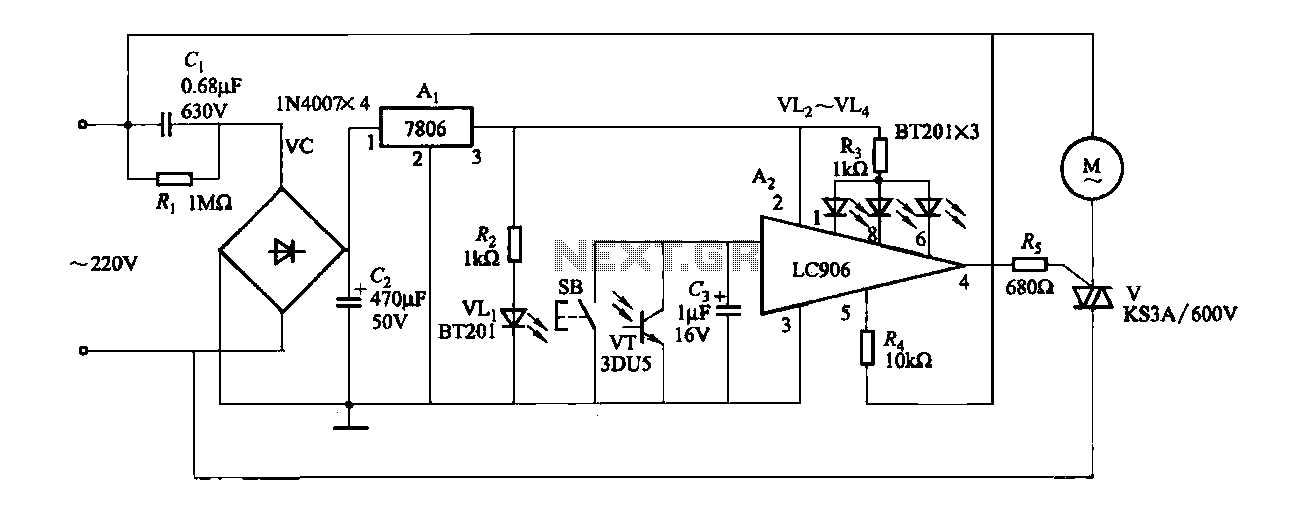
The ceiling fan speed control circuit is designed to modulate the speed of a ceiling fan using a combination of a capacitor step-down method and a voltage regulation approach. The circuit incorporates a three-terminal fixed voltage regulator, specifically the 7806, which provides a steady output voltage of 6V. This stable voltage is essential for the reliable operation of the integrated circuit A2, which manages the fan speed.
The control mechanism involves a Triac, designated as V, which regulates the power delivered to the fan motor by altering its conduction angle. The conduction angle is the portion of the AC cycle during which the Triac is turned on, thereby controlling the amount of power supplied to the fan. By adjusting this angle, the fan speed can be varied smoothly.
User interaction with the circuit is facilitated through a push-button switch, labeled SB. When pressed, this switch initiates a sequence in which the integrated circuit A2 cycles through predefined speed settings. This cycling allows for multiple speed options, typically ranging from low to high, and includes an off setting. Each speed corresponds to a specific conduction angle, with lower speeds achieved by reducing the conduction angle, thus providing a finer control over the fan's operation.
This circuit design exemplifies a practical application of power electronics in home appliances, demonstrating how simple components can work together to achieve efficient and user-friendly control of ceiling fan speeds. Proper implementation of this circuit ensures that the fan operates quietly and efficiently at the desired speed, enhancing comfort in living spaces.Fans (Ceiling) Fifth gear speed control circuit shown in Figure 3-6. It uses capacitor step-down, three-terminal fixed 7806 integrated steady voltage regulator Ai regulator to achieve fan speed control integrated circuit A2 through LC906 control Triac V conduction angle. Order press the button SB. A2 will be 4 feet by a block 1 block 2 block -3 -4 -5 stop a block off a one block. cycling issue a control signal, so that V conduction block smaller race, to achieve speed.
Related Circuits
This is a car alarm simulator that uses an LED as a simulation output. This simple circuit can indicate whether a car is running or not by detecting the voltage difference when the car is on or off. This...
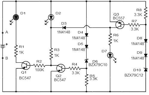
When the battery voltage is 11.5V or less, transistor Q1 is activated, and LED D1 will illuminate. When the battery voltage is between 11.5V and 13.5V, transistor Q2 is activated, causing LED D2 to light up. At a battery...
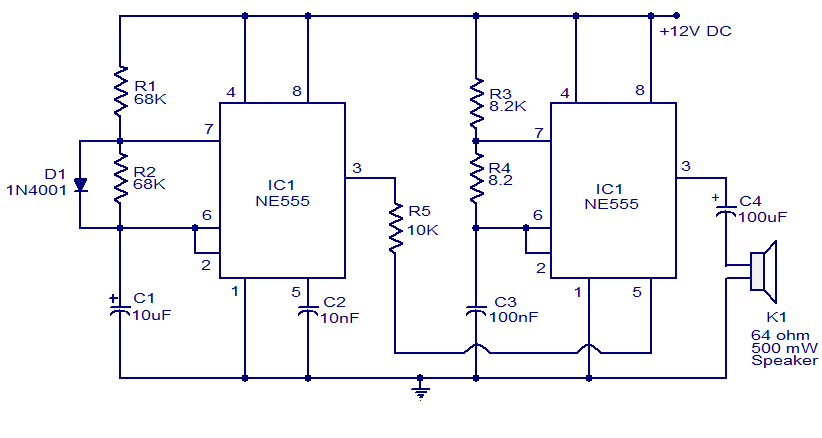
A variety of electronic circuits utilize the NE555 timer integrated circuit (IC). The circuit diagram presented illustrates a police siren based on two NE555 timer ICs, both configured as astable multivibrators. The circuit operates on a DC voltage supply...
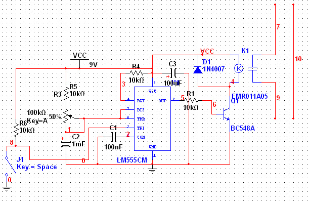
The 555 Timer has extensive applications in electronics. This document describes the use of the 555 Timer in a monostable multivibrator configuration to trigger a transistor driver that energizes a relay, which in turn operates a 230V AC lamp...
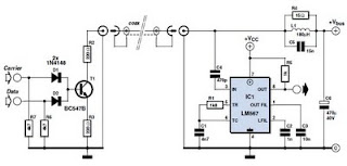
This circuit was designed to transmit commands over an LNB coaxial cable. An LNB (Low-Noise Block downconverter) is commonly used for satellite TV reception and is positioned at the focal point of a satellite dish. The circuit generates a...
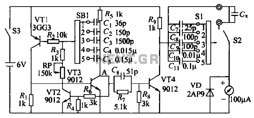
A capacitive measuring instrument is a direct reading device that measures the capacitance of a circuit. This instrument is capable of measuring capacitance values ranging from a few picofarads to 0.1 microfarads, with specific ranges of 25 pF, 100...